Download
1 / 25
1.2k likes | 2.99k Views
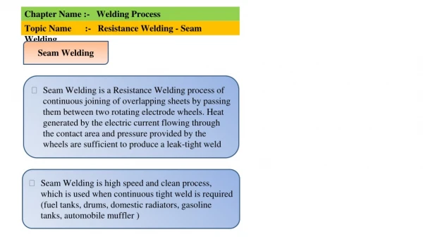
Resistance Welding. Commonly used resistance welding processes: Resistance Spot Welding (RSW), Resistance Seam Welding (RSEW),& Resistance Projection Welding (PW) or (RPW)

E N D
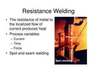
Resistance Welding Commonly used resistance welding processes: • Resistance Spot Welding (RSW), • Resistance Seam Welding (RSEW),& • Resistance Projection Welding (PW) or (RPW) • Resistance welding uses the application of electric current and mechanical pressure to create a weld between two pieces of metal. Weld electrodes conduct the electric current to the two pieces of metal as they are forged together.
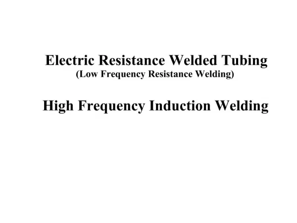
The welding cycle must first develop sufficient heat to raise a small volume of metal to the molten state. This metal then cools while under pressure until it has adequate strength to hold the parts together. The current density and pressure must be sufficient to produce a weld nugget, but not so high as to expel molten metal from the weld zone. • High Frequency Resistance Welding (HFRW) Percussion Welding (PEW) and Stud Welding (SW), too.
H = I2 R t K • K- energy losses through radiation & conduction • resistances of the electrodes • electrode- w/p contact resistance • resistance of the individual parts to be welded • w/p-w/p contact resistance (maintained high) Electrode Weld Nugget Resistance Welding Benefits • High speed welding • Easily automated • Suitable for high rate production • Economical HAZ Electrode
Resistance Welding Limitations • Initial equipment costs • Lower tensile and fatigue strengths • Lap joints add weight and material • Common Resistance Welding Concerns • Optimize welding process variables. • Evaluate current welding parameters and techniques. • And thus eliminate common welding problems and discontinuities - such as
Resistance Welding Problems and Discontinuities • Cracks • Electrode deposit on work • Porosity or cavities • Pin holes • Deep electrode indentation • Improper weld penetration • Surface appearance • Weld size • Irregular shaped welds
RESISTANCE SPOT WELDING • AIR OPERATED ROCKER ARM SPOT WELDING MACHINE
RESISTANCE SPOT WELDING ELECTRODE DESIGNS FOR EASY ACCESS INTO COMPONENTS
FLASH WELDING FOR SOLID RODS & TUBES DESIGN GUIDELINES POOR GOOD
DISTORTION • Welding involves highly localized heating of the metal being joined together. • The temperature distribution in the weldment is nonuniform. • Normally, the weld metal and the heat affected zone (HAZ) are at temperatures substantially above that of the unaffected base metal. • Upon cooling, the weld pool solidifies and shrinks, exerting stresses on the surrounding weld metal and HAZ. • If the stresses produced from thermal expansion and contraction exceed the yield strength of the parent metal, localized plastic deformation of the metal occurs. • Plastic deformation results in lasting change in the component dimensions and distorts the structure. This causes distortion of weldments.
Types of distortion • Longitudinal shrinkage • Transverse shrinkage • Angular distortion • Bowing • Buckling • Twisting
Factors affecting distortion • If a component were uniformly heated and cooled distortion would be minimized. However, welding locally heats a component and the adjacent cold metal restrains the heated material. This generates stresses greater than yield stress causing permanent distortion of the component. Some of the factors affecting the distortion are: • Amount of restraint • Welding procedure • Parent metal properties • Weld joint design • Part fit up
Restraint - to minimize distortion. Components welded without any external restraint are free to move or distort in response to stresses from welding. It is not unusual for many shops to clamp or restrain components to be welded in some manner to prevent movement and distortion. This restraint does result in higher residual stresses in the components. • Welding procedure impacts the amount of distortion primarily due to the amount of the heat input produced. The welder has little control on the heat input specified in a welding procedure. This does not prevent the welder from trying to minimize distortion. While the welder needs to provide adequate weld metal, the welder should not needlessly increase the total weld metal volume added to a weldment.
Parent metal properties, which have an effect on distortion, are coefficient of thermal expansion and specific heat of the material. The coefficient of thermal expansion of the metal affects the degree of thermal expansion and contraction and the associated stresses that result from the welding process. This in turn determines the amount of distortion in a component. • Weld joint design will effect the amount of distortion in a weldment. Both butt and fillet joints may experience distortion. However, distortion is easier to minimize in butt joints. • Part fit up should be consistent to fabricate foreseeable and uniform shrinkage. Weld joints should be adequately and consistently tacked to minimize movement between the parts being joined by welding.
Welding DiscontinuitiesSome examples of welding discontinuities are shown below. Evaluation of the discontinuity will determine if the discontinuity is a defect or an acceptable condition Incomplete Fusion - A weld discontinuity in which fusion did not occur between weld metal and fusion faces or adjoining weld beads.
Undercut - A groove melted into the base metal adjacent to the weld toe or weld root and left unfilled by weld metal. Overlap - The protrusion of weld metal beyond the weld toe or weld root.
Underfill - A condition in which the weld face or root surface extends below the adjacent surface of the base metal. Incomplete Joint Penetration - A joint root condition in a groove weld in which weld metal does not extend through the joint thickness • Partial joint penetration groove welds are commonly specified in lowly loaded structures. However, incomplete joint penetration when a full penetration joint is required, as depicted above, would be cause for rejection. A fix for an incomplete penetration joint would be to back gouge and weld from the other side. Another acceptable partial penetration joint is shown below.
Partial penetration joint on the left without discontinuities is an acceptable condition. Appropriate engineering decisions need to be applied to determine what type of joint should be specified for a given application.
Representation of a convex fillet weld without discontinuities