Download
1 / 157

E N D
Electromagnetic Testing - Eddy Current Instrumentation 2014-December My ASNT Level III Pre-Exam Preparatory Self Study Notes 外围学习中 Charlie Chong/ Fion Zhang
Charlie Chong/ Fion Zhang http://microwavesoft.com/eddycurrent.html
激发我更加的努力学习 激发我更加的努力学习. Charlie Chong/ Fion Zhang
Fion Zhang at Shanghai 2014/November http://meilishouxihu.blog.163.com/ Shanghai 上海 Charlie Chong/ Fion Zhang
甪直古镇 甪直古镇 Charlie Chong/ Fion Zhang
Shanghai 上海七宝古镇 上海七宝古镇 Charlie Chong/ Fion Zhang
Greek letter Charlie Chong/ Fion Zhang
Expert at works Charlie Chong/ Fion Zhang
Pipeline Remote Field Testing Charlie Chong/ Fion Zhang
Experts at work Charlie Chong/ Fion Zhang
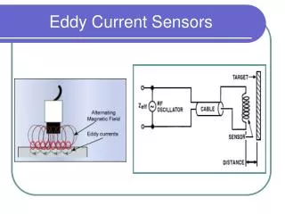
3.0 INSTRUMENTATION 3.1. Principles and basic characteristics of eddy current probes Eddy current probes are based on relatively simple principles and usually consist of an assembly containing one or more coils in a suitable configuration. The shape of the coil, its cross-section, size, and configuration are parameters that need to be considered to produce a particular probe suitable for a specific application or range of applications. This coil is energized by an alternating current of known frequency and amplitude which gives rise to the magnetic field which is also of varying type. When this coil is brought closer to a conductive test material, there is an induced voltage generated in the sample. Note: There is no Chapter 1 & 2. Charlie Chong/ Fion Zhang
3.1.1 Induction and Reception Function There are two methods of sensing changes in the eddy current characteristics: (a) The impedance method (b) The send receive method Impedance method In the impedance method, the driving coil is monitored. As the changes in coil voltage or a coil current are due to impedance changes in the coil, it is possible to use the method for sensing any material parameters that result in impedance changes. The resultant impedance is a sum of the coil impedance (in air) plus the impedance generated by the eddy currents in the test material. The impedance method of eddy current testing consists of monitoring the voltage drop across a test coil. The impedance has resistive and inductive components. The impedance magnitude is calculated from the equation: |Z| = [ R2+ (XL)2 ] ½(Xcwas assume nil) Where: Z = impedance, R = resistance, XL= inductive reactance Charlie Chong/ Fion Zhang
and the impedance phase is calculated as: θ θ = tan-1(XL/ R) Where: θ = phase angle, R = resistance, XL= inductive reactance The voltage across the test coil is V= IZ, where I is the current through coil and Z is the impedance. Charlie Chong/ Fion Zhang
A test sample’s resistance to the flow of eddy currents is reflected as a resistive load and is equivalent to a resistance in parallel to the coil inductive reactance. This load results in a resistive and inductive impedance change in the test coil. Coil impedance can be displayed on normalized impedance diagrams. With this display we can analyse the effect of sample and test parameters on coil impedance. The equivalent circuit derivation of coil impedance is useful for a quantitative understanding of the effect of various test parameters. Keywords: The impedance method of eddy current testing consists of monitoring the voltage drop across a test coil. Coil impedance can be displayed on normalized impedance diagrams. Charlie Chong/ Fion Zhang
Impedance Phasol Diagrams Charlie Chong/ Fion Zhang http://hyperphysics.phy-astr.gsu.edu/hbase/electric/impcom.html
Impedance Phasol Diagrams , ω = 2πf Charlie Chong/ Fion Zhang http://hyperphysics.phy-astr.gsu.edu/hbase/electric/rlcser.html
Eddy Current Testing Displays http://idea- ndt.en.alibaba.com/product/492 408541- 212402655/Copper_tube_and_s teel_wire_rope_on_line_eddy_c urrent_tester.html Charlie Chong/ Fion Zhang
3.1.2 Mode of Operation 3.1.2.1 Send receive mode (Reflection Probes) The send-receive method consists of separate driving coil (or coils) and pick- up coil (or coils). In this case, the induced voltage across the pick-up coil is measured. The send-receive method in eddy current testing is used to eliminate the temperature drift. The flow of eddy currents is monitored by observing the effect of their associated electromagnetic fields on the voltage induced in an independent receiver coil(s). This is shown in FIG. 3.1. Charlie Chong/ Fion Zhang
The excitation or primary coil is driven with a sinusoidal current with constant peak to peak amplitude to obtain a constant magnetomotive force. As a result the flux of the excitation coil is independent of coil resistance. The wire resistance of both the excitation and receiver coils can change, because of temperature, without affecting the output signals. The effect of temperature drift is thus eliminated. Temperature independence makes this method useful for measuring conductivity, wall thickness and spacing between metal layers. Keywords: The send-receive method in eddy current testing is used to eliminate the temperature drift. (How?) Charlie Chong/ Fion Zhang
Question: How the send-receive method in eddy current testing is used to eliminate the temperature drift? Charlie Chong/ Fion Zhang
3.1.2.2 Absolute and differential measurements. The most basic distinction between probes can be made based on their mode of operation. This includes: (a) Absolute eddy current probes. (b) Differential eddy current probes. Absolute Eddy Current Measure Absolute eddy current probes consist of a single coil or its equivalent. A winding separated into two or more sections, would still be considered absolute if it performs as such. In this type of probe, the impedance or the induced voltage in the coil is measured directly (their absolute values rather than changes in impedance or induced voltage). FIG. 3.2 and FIG. 3.3 show absolute eddy current probes. Charlie Chong/ Fion Zhang
Absolute Probes FIG. 3.2. Single-coil absolute arrangement. FIG. 3.3. Double-coil absolute arrangement. Charlie Chong/ Fion Zhang
Question: Is this not a reflection probe? Exciting coil? Receiving coil? Typical Reflection coil set-up Charlie Chong/ Fion Zhang
In the single coil absolute arrangement, it will test only the area under coil and does not compare itself with a reference standard (external reference). As was observed in Fig. 3.3 for double coils, the secondary coil has the indicating device connected across the coil and is not connected to an AC source. Normally the secondary coil is located inside the primary coil and the two coils are referred to as a double coil. When double coils are used the primary coil generates or induces eddy currents into the article. The eddy currents in turn, generate a magnetic field that reacts against the field of the primary coil and also induces a current into the secondary coil. Changes in eddy current flow are reflected as changes in the current induced in the secondary coil. Thus the indicating device presents the change in eddy current flow. The double coil absolute arrangement is also known by names such as, driver pickup probe, driver driven probe, pitch catch probe and, more commonly, a reflection probe. ← ← (Answer) Charlie Chong/ Fion Zhang
3.1.2.3 Differential eddy current measurements. Differential eddy current probes consist of a pair of coils connected in opposition so that a net measured impedance or induced voltage is cancelled out when both coils experience identical conditions. The coils can sense only changes in the material under test, therefore differential eddy current probes are used to react to changes in test materials while cancelling out noise and any unwanted signals that affect both coils. FIG. 3.4 shows a typical single coil self comparison differential arrangement and FIG. 3.5 shows a typical single coil external reference differential arrangement. FIG. 3.6 shows a typical double coil self comparison differential arrangement and FIG. 3.7 shows a typical double coil external reference differential arrangement. Charlie Chong/ Fion Zhang
FIG. 3.4. Single coil self comparison differential arrangement. Note: The single coils arrangement: absolute coil arrangement. Charlie Chong/ Fion Zhang
FIG. 3.5. Single coil external comparison differential arrangement. Note: The single coils arrangement: absolute coil arrangement. Charlie Chong/ Fion Zhang
FIG. 3.6. Double coil self comparison differential arrangement. Note: The double coils arrangement: Reflection coil arrangement. Charlie Chong/ Fion Zhang
FIG. 3.7. Double coil external comparison differential arrangement. Note: The double coils arrangement: Reflection coil arrangement. Charlie Chong/ Fion Zhang
Keywords: Single coil Double coils Self comparison External comparison Charlie Chong/ Fion Zhang
Question: What is this arrangement? Single coil self comparison differential arrangement. Charlie Chong/ Fion Zhang
Question: What is this arrangement? Single coil self comparison differential arrangement. Charlie Chong/ Fion Zhang
Comparison between absolute and differential probes Absolute Differential 1. Sensitive to both sudden and gradual changes in properties and dimensions. 1. Not sensitive to gradual changes in properties of dimensions (may not sense long gradual flaws). 2. Combined signals are usually easy to interpret. 2. Signals could be difficult to interpret. 3. Show total length of flaws. 3. Detect only ends of long flaws. 4. Sensitive to drift from temperature changes. 4. Not Sensitive to drift from temperature changes 5. Sensitive to probe wobble. 5. Less Sensitive to probe wobble Charlie Chong/ Fion Zhang
Exercise 作业 作业. Describe; Absolute, Reflection coil arrangement. Types of differential coil arrangement. Charlie Chong/ Fion Zhang
3.1.3 Probe Configuration: Types of probe The eddy current probes can have a variety of forms. The choice of the type depends upon the test situation. Following are the three major types of probe mainly used in eddy current testing: (a) Internal (bobbin type) probe. (b) Encircling probe. (c) Surface probe. Charlie Chong/ Fion Zhang
3.1.3.1 Internal probe Internal probes consist of circular coils used to test the interior of tubes or circular holes. FIG. 3.8 illustrates a type of coil which can be inserted into a tube to inspect discontinuities on the inner circumference of the tube. As with the encircling coil, the internal coil induces currents that encircle the entire circumference of the tube so that the entire section surrounding the coil is inspected. As the currents induced in the material are strongest near the coil, the internal coil is more sensitive to defects lying on or near the inner surface of the tube. Pipe FIG. 3.8. Internal coil. Charlie Chong/ Fion Zhang
Bobbin Probe Charlie Chong/ Fion Zhang
Internal Probe Charlie Chong/ Fion Zhang
3.1.3.2 Encircling probes Encircling probes are similar in structure to internal probes except for the fact that the test material is passed inside the coils. They are primarily used to inspect the outside surface of round materials such as tubes and rods. FIG 3.9. shows an encircling coil. The magnetic field induces eddy currents in the bar that encircle the entire circumference of the tube or rod so that the entire section under the coil is inspected at any one instance. The width of the coil is a function of the application. Wide coils cover large areas, so they respond mostly to bulk effects, e.g. conductivity, whereas narrow coils sense small areas and so are more responsive to small changes such as those produced by discontinuities. The magnetic field of the coil extends slightly beyond the ends of the coil. Charlie Chong/ Fion Zhang
FIG. 3.9. Encircling coil. Charlie Chong/ Fion Zhang
Encircling coil. (Reflection double coil mode) Charlie Chong/ Fion Zhang http://www.duiliogessi.com/ndt.html
3.1.3.3 Surface probes Surface probes are one of the most widely used eddy current probes for inspecting surfaces, flat or contoured for defects or material properties. Defects can either be surface or subsurface. These are also called probe coils. FIG. 3.10 shows a typical surface probe. The surface probe may be hand held or mounted in automated scanning equipment. The coil mounted in the end of the probe is provided with a protective coating of epoxy to serve as a wear surface. The magnetic field produced by a coil is approximately of the size of the coil. Other variations of surface probe designs are pancake probe, flat probe, horse shoe or gap probe, spring loaded probe spinning probe and pencil probe. Charlie Chong/ Fion Zhang
FIG. 3.10. A typical surface probe. Charlie Chong/ Fion Zhang
Surface probe. Charlie Chong/ Fion Zhang
Summary: Mode of operation: Absolute → Single coil, double coil (differential) Reflection → Send & Pick-up Configuration: Surface Bobbin (internal) Encircling Charlie Chong/ Fion Zhang
3.2. Eddy current distribution relative to coil position 3.2.1 Field Generated by Non-load Inductor Coil In the case of a long straight conductor carrying current, the lines of magnetic force (or flux) exist which are closed circular paths concentric with the axis of the conductor. The relative permeability of air and non-magnetic materials for all practical purposes is considered to be 1. In case of ferromagnetic materials the relative permeability is not constant but is a function of flux density. However, for eddy current probe energized by low levels of magnetization, the permeability can be considered reasonably constant. Now when the straight wire is wound into a coil (many loops of wire), the lines of the force encircling the wire form a magnetic field inside and outside the loop as illustrated in FIG. 3.11. Charlie Chong/ Fion Zhang
Line of magnetic flux around a straight conductor carrying current. The lines of magnetic force (or flux) exist which are closed circular paths concentric with the axis of the conductor. Charlie Chong/ Fion Zhang