Download
1 / 28
280 likes | 382 Views
UML – Unified Modelling Language For Effective OO Development. Yves Holvoet Rational Software Corporation. (say Eve Olvoot). Agenda. Modelling Why? Levels of Abstraction 5 Views and 2 dimensions of System Architecture UML History 10 diagrams Summary. The Importance of Modeling.

E N D
UML – Unified Modelling LanguageFor Effective OO Development Yves Holvoet Rational Software Corporation (say Eve Olvoot)
Agenda • Modelling • Why? • Levels of Abstraction • 5 Views and 2 dimensions of System Architecture • UML • History • 10 diagrams • Summary
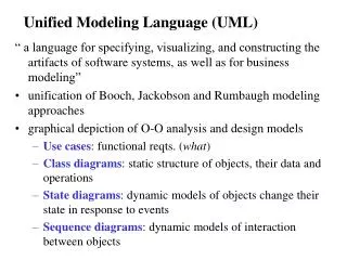
What Is a Model? • A model is a simplification (abstraction) of reality.
Abstraction • Is conceptual and captures the essential characteristics of an entity that distinguish it from all other kinds of entities. • Defines a boundary relative to the perspective of the viewer.
Instance myAccount : BankAccount yourAccount : BankAccount • Is an actual entity instance of the conceptual abstraction. • All instances of a given abstraction share a common structure (data and behavior as described in the Abstraction).
Levels of Abstraction Scenario High Level object object Is an instance of Is an abstraction for Low Level Processor Processor Type
Modeling Process Modeling Process Business Business Business Use Cases - Activities Business Use Cases - Activities High Level Use Cases Scenarios Classes Objects System Abstraction Instance Sources Processes Processors Low Level
UML 1 + 2 * 2 Views Layers Use Cases Packages Scenarios Logical View Use Case View Classes Objects Software Implementation View Sources Process View Tasks Packages Processes Layers Systems Hardware Deployment View Processors
4 + 1 = 1 + 2 * 2 Views Logical View Logical View Use Case View Implementation View Implementation View Use Case View Deployment View Deployment View Process View Process View • The Use-Case view describes the behavior of the system in term of use-cases and scenarios • The Logical view packages the classes of the system and their relationships • The Implementation view describes the mapping of the logical classes to components of the target environment • The Process view deals with concurrency and synchronization • The Deployment view describes the mapping of the software on the hardware
Use-Case View Specification Class Validation DevelopmentPlan • 3MainBenefits Abstraction for many scenarios message instance of operation link instance of association object instance of class
Use Case View: Main Benefits • Specification • in terms of use cases • Development plan • lists iterations • assign scenarios to iterations according to their risk levels • Validation of classes • the necessary objects for the whole system are collectively all the objects participating in all scenarios • the messages between objects drive class relationships
Logical View Terminology Object Validation Development Teams • 3 Main Benefits Logical grouping of classes Strong inner coupling (cohesive classes) Weak outer coupling (for reuse, resilience)
Logical View: Main Benefits • Terminology • it provides vocabulary for common unambiguous understanding of the problem domain • Development Teams • they are derived from packages • packages are created to minimize the coupling • Validation of objects • the objects, links and messages must be in synch with class, relationships and operations
2 Dimensions for Software Architecture Logical packages form horizontal layers where layers can only access what is below and not what is above Scenarios form vertical slices where each slice traverses all layers but only “hits” a small sub-set of the classes Rational Unified Process is: Architecture Centric Use Case Driven
Agenda • Modelling • Why? • Levels of Abstraction • 5 Views and 2 dimensions of System Architecture • UML • History • 10 diagrams • Summary
History of the UML Nov ‘97 UML approved by the OMG
UML Concepts • The UML may be used to visually model: • The interaction of your application with the outside world • Use Case Diagram • The behavior of your system • Interaction Diagram • The structure of your system • Class Diagram • Package Diagram • The components in your system • Component Diagram • Deployment Diagram
10 UML Diagrams Activity Diagram Sequence Diagram Use Case Diagram Interaction Diagram (Scenarios) Collaboration Diagram Class Diagram (static part of class) State-Transition Diagram (behavioral part of class) Object Diagram Component Diagram (Sources & Processes) Deployment Diagram (Processors)
Use Case Diagram Request Course Roster Professor Student Register for Courses Billing System Maintain Course Information Registrar • Use case diagrams are created to visualize the interaction of your system with the outside world
Sequence Diagram registration registration math 101 : Student math 101 form manager section 1 1: fill in info 2: submit 3: add course(joe, math 01) 4: add(Joe) 5: are you open? 6: add (Joe) • A sequence diagram shows step-by-step what has to happen to accomplish a piece of functionality provided by the system
Collaboration Diagram course form : 1: set course info CourseForm 2: process 3: add course : Registrar theManager : aCourse : CurriculumManager Course 4: new course • A collaboration diagram displays object interactions organized around objects and their links to one another
Class Diagram RegistrationUser Student major Professor 3..10 CourseOffering 4 1 0..4 • A class diagram shows the structure of your software
2 Main Relationships: Inheritance vs. Association Person Food <<deferred>> eat(Food) Vegan Vegetarian Omnivore eat(Food) eat(Food) eat(Food) pre-condition of eat() is: pre-condition of eat() is: No pre-condition at all for -Food parameter must be a -Food parameter must be either a eat() Vegetable Vegetable or Derived from Animal
The Physical World Register.exe Billing.exe Billing System People.dll User Course.dll Course • Component diagrams illustrate the organization and dependencies among software components
Deploying the System Registration Database Main Library Building Dorm • The deployment diagram visualizes the distribution of components across the enterprise.
Summary • Visual modeling can be used to: • Define business process • Communicate • Manage complexity • Define software architecture • Promote reuse • The UML is the standard language for visualizing, specifying, constructing, and documenting the artifacts of a software-intensive system