Download

1 / 22
220 likes | 360 Views
Table of contents. Thermo- Compound -Installation. 1. The concept. 2. The principle. 3. The advantage. 4. Option. 5. E xample Thermo- Compound - Installation. Thermo- Compound -Installation. Semi- automatic combination of Hot-Smoking and Intensive Cooling.

E N D
Table ofcontents Thermo-Compound-Installation 1. The concept 2. The principle 3. The advantage 4. Option 5. Example Thermo-Compound- Installation
Thermo-Compound-Installation Semi-automaticcombinationof Hot-Smoking and Intensive Cooling
Thermo-Compound-Installation Scheme
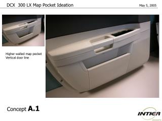
Thermo-Compound-Installation Dooroptions
Thermo-Compound-Installation New designedelectricaltransport The concept of “two hands” is continued down to the pusher. The heavy design assures functionality even when strongly soiled.
Thermo-Compound-Installation New designedelectricaltransport • Guided transport through the door:The fork beam in the heating chamber pushes- with two hands - the trolley through the doors • The beam ofthecoolingchamberpicksupthetrolley
Thermo-Compound-Installation New designedelectricaltransport The transport beam of the heating chamber is pushing the trolleys into the cooling chamber. The beam of the heating chamber remains in position until the cooling chamber beam has catched the trolley.
Thermo-Compound-Installation New designedelectricaltransport • Technical data • Power consumption 0,75 kW • Minimum sizeofthechamber1x3 or 2x3 • Maximum sizeofthechamber1x12 or 2x10 • Maximum loadofthetrolley 1 ton • Wearpartsstandardchain 1“
Thermo-Compound-Installation New designedelectricaltransport Distance between the floor and the H-beam of the smoke trolley Distance: minimum 220 mm and maximum 260 mm
Thermo-Compound-Installation • Batch loadingandunloadingcanberealisedbyonepersononly • Smooth transportoftrolleyswithhighestcharging • Uninteruptedtransportationoftrolleysfromsmokingtocooling • Automatictransition (smoking / cooling) • Robust andprecise design
Thermo-Compound-Installation Advantages • Slight time ofbacterialcontamination due tofast passingofthecriticaltemperaturerangeof +40 °C upto +15 °C • Extended shelflife • Unloadingcanberealisedbyonepersononly • No extra spacesforcoolingtheproductsareneeded • Minimum lossofweight, i.e. costsavings • Slightcleaningeffortsofcoolingareaandtrolleys + accessories • Lowerquantityoftrolleys, accessoriesandemployees
Thermo-Compound-Installation References unitl 2013
Thermo-Compound-Installation References
Thermo-Compound-Installation References
Thermo-Compound-Installation Option: Pre-coolingofwaterfor Intensive Cooling
Thermo-Compound-Installation Characteristics • Watertemperatures >+15 °C • Reductionofshowertimes • Reductionofwaterconsumption • Showerwater +1 °C independentofseason • Identicalshowertimes • Coolingagentonlyglycol (e.g. ethylene, propylene) • Flow temperatureiscontrolledby VEMAG to – 2°C • Pump andthree-waycontrolvalve VEMAG • Isconnectedtostandardshower • Level showerincreaseswaterconsumption • Showercanalternativelyusedwithoutpre-cooling • Showerwateris lost water (norecyclingpossible)
Thermo-Compound-Installation Example
Thermo-Compound-Installation Example
Thermo-Compound-Installation Example