Download
1 / 30
300 likes | 438 Views
Fourth LACCEI International Latin American and Caribbean Conference for Engineering and Technology (LACCET’2006) 21-23 June 2006, Mayagüez, Puerto Rico. Overview. Objective Hardware Verification Methodology API and Sample C++ Test Vector Source Code Sample Test Vector Stimulus File

E N D
Fourth LACCEI International Latin American and Caribbean Conference for Engineering and Technology (LACCET’2006)21-23 June 2006, Mayagüez, Puerto Rico
Overview • Objective • Hardware Verification Methodology • API and Sample C++ Test Vector Source Code • Sample Test Vector Stimulus File • 4-Bit Slice Microprocessor Block Diagram • Sampling of Simulation Results • Conclusion
Objective • Implementation of a 4-bit Microprocessor • with the following capabilities: • Read 4-bit digital word from memory RAM • Internal modules: • 4 bit Registers (A, B, C, D) • ALU • Instruction Decoder • Multiplexer • RAM • Instructions Set: ADD, SUB, CMP, SHL, • SHR, ROL, ROR, AND, OR, NOT
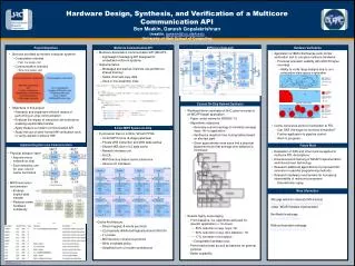
Industry Hardware Functional Verification Methodology C++ API Implementation method call Test Vector C++ Source Code Stimulus test vector C++ Model Simulation Hardware RTL Simulation Mentor Graphics Waveform C Model result files RTL result files Comparison Scripts Pass/Fail
Hardware Verification Methodology C++ API Implementation contains method calls used in the test vector C++ source code for stimulus test vector generation. Test Vector C++ Source Code are written to generate stimulus test vector to test the hardness of the 4-bit slice microprocessor features. The test vector is read by the microprocessor RTL testbench. Hardware RTL Simulation used Mentor Graphics tools to read, compile, and simulation input/output signals for analysis based on the stimulus test vector. Mentor Graphics Waveform files where capture based on the select signals Under investigation. C++ API Implementation method call Test Vector C++ Source Code Stimulus test vector Hardware RTL Simulation Mentor Graphics Waveform
Sample C++ Test Vector Source Code #include <iostream.h> …………….. #include "test_api.h" int main () { enum opcode {ADD, SUB, CMP, SHL, SHR, ROL, ROR, AND, OR, NOT, MOVA, MOVB, MOVC, MOVD}; int RegAB = 0x3; int RegAC = 0x5; int RegAD = 0x9; class instruction_api iss_api("test_opcode.in"); //load memory iss_api.setADD(0x0, 0x5,0x7); iss_api.setSUB(0x2, 0x7,0x3); iss_api.setCMP(0x4, 0x3,0x2); //do instructions iss_api.setMOVA(iss_api.getaddrADD()); iss_api.setMOVB(iss_api.getaddrADD() + 1); iss_api.Execute(RegAB,ADD); iss_api.Execute(RegAB,SUB); ……………….. }
Sample Test Vector Stimulus File A test vector stimulus file is generated to be read by the microprocessor test bench. This format of this file is the following: <w> <addr> <data> -- load memory to RAM <i> <reg sel> <addr> <opcode> --instruction of opcode to be performed The following is an example of a Test Vector Stimulus File: w 0000 0101 w 0001 0111 w 0010 0011 w 0011 0111 ... i 000100001010 i 001000011011 i 001100000000 i 001100000001
4-bit Slice Microprocessor Block Diagram instruction instruction[7:4] clk RAM instruction[11:8] reset addr data we rdata instruction[3:0] Instruction Decoder rega wrb regb regc wrd regd wra wrc rega regb regc regd rega_data regb_data regc_data regd_data sel MUX D S instruction[3:0] ALU C4 C
Tools Used Picture Courtesy: Mentor Graphics
4-bit Slice Microprocessor Synthesized System Level Diagram
4-bit Slice Microprocessor Top Level Entity - VHDL Code ----------------------------------------------------------------- -- Title : VHDL style -- File name : MicroProcessor.vhd -- Authors : Vivek Jayaram, Subbarao Wunnava -- Description : This Program describes the top level entity of -- the Microprocessor. ----------------------------------------------------------------- library IEEE; use IEEE.STD_Logic_1164.all; use IEEE.numeric_std.all; entity MicroProcessor is port(reset : in std_logic; clk : in std_logic; instruction: in unsigned(11 downto 0); addr : in unsigned(3 downto 0); data : in unsigned(3 downto 0); we : in std_logic; C0 : in std_logic; C : inout unsigned(3 downto 0); C4 : out std_logic); end MicroProcessor;
4-bit Slice Microprocessor Top Level Diagram
Instruction Decoder (Top Level Diagram)
RTL Schematic Instruction Decoder
ALU (Top Level Diagram)
RAM (Top Level Diagram)
Microprocessor Timing Diagram: Preload Memory Phase
Instruction Phase Add & Subtract Operations
Instruction Phase Shift Logic Left Operation
Instruction Phase Shift Rotate Right & AND Operation
Speed of Operation Critical Path Delay = 69.1 nsec Fmax = 1 / Critical Path = 14.47 Mhz
Total accumulated area : Number of Clock Buffers 2 Number of Combinational modules 280 Number of GND 54 Number of INBUF 22 Number of OUTBUF 5 Number of Sequential modules 24 Number of VCC 56 Number of modules 300 Number of accumulated instances 443 A1240XLPG132 (Actel-FPGA)
Resource Used Avail Utilization -------------------------------------------------------------- IOs 29 104 27.88% Modules 300 684 43.86% Sequential modules 24 348 6.90% Combinational modules 280 336 83.33% -------------------------------------------------------------- Device Utilization for A1240XLPG132 (Actel-FPGA)
Relative Power The Relative Power for one unit is calculated by the formula: P = E/T = E * f * duty_cycle Ptotal = n * P where, Where, n is the Transistor Count. In our case, E = 0.5 * C * V2 Where, ‘C’ is the cell capacitance for 1 unit (10–15 farads)( approximated) & ‘f ’ is the frequency of operation = 14.47 Mhz We have: Sequential modules : 24 x 40 transistors = 960 ( Appr.) Combinational modules: 280 x 10 transistors = 2800 Total = 3760 (Approximated Value ) Total Power: ( 6.25 x 10⁻¹⁵ ) x (f) x ‘n’ = ( 6.25 x 10⁻¹⁵ ) x (14.47 x 10⁶ ) x 3760 = 0. 3 mw
Conclusions • Our API enables us to write multiple test vectors for • different test scenarios • Test bench is able to read in any test vector • VHDL code is written in a structural fashion • Therefore, can easily be modified for higher order • microprocessor system • 29 Pins for address/data, memory & others • 0.3 mw power dissipation • This module can be implemented successfully • in Actel’s FPGA module A1240XLPG132
Thanks for the Attention