Download
1 / 25
250 likes | 457 Views
INC 112 Basic Circuit Analysis. Week 10 RLC Circuits. RLC Circuits. Similar to RL and RC circuits, RLC circuits has two parts of responses, namely: natural response and forced response. Force Response: Similar to RL and RC, a step input causes a step output. Natural Response:

E N D
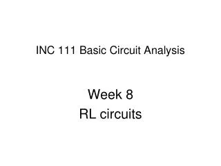
INC 112 Basic Circuit Analysis Week 10 RLC Circuits
RLC Circuits Similar to RL and RC circuits, RLC circuits has two parts of responses, namely: natural response and forced response. Force Response: Similar to RL and RC, a step input causes a step output. Natural Response: Different and more difficult than RL, RC.
Second-order Differential equation Source-free RLC Circuits We study the natural response by studying source-free RLC circuits. Parallel RLC Circuit
This second-order differential equation can be solved by assuming solutions The solution should be in form of If the solution is good, then substitute it into the equation will be true. which means s=??
Use quadratic formula, we got Both and are solution to the equation Therefore, the complete solution is
From Define resonant frequency Damping factor Therefore, in which we divide into 3 cases according to the term inside the bracket
Solution to Second-order Differential Equations • α > ω0 (inside square root is a positive value) Overdamped case • α = ω0 (inside square root is zero) Critical damped case • α < ω0 (inside square root is a negative value) Underdamped case
1. Overdamped case , α > ω0 Find v(t) Initial condition vc(0) = 0, iL(0) = -10A α > ω0 ,therefore, this is an overdamped case s1 = -1, s2 = -6
Therefore, the solution is in form of Then, we will use initial conditions to find A1, A2 From vc(0) = 0 we substitute t=0 From KCL At t=0
Solve the equation and we got A1 = 84 and A2 = -84 and the solution is v(t) t
2. Critical damped case , α = ω0 Find v(t) Initial condition vc(0) = 0, iL(0) = -10A α = ω0 , this is an critical damped case s1 = s2 = -2.45 The complete solution of this case is in form of
Then, we will use initial conditions to find A1, A2 From vc(0) = 0 we substitute t=0 Therefore A2 =0 and the solution is reduced to Find A1 from KCL at t=0
Solve the equation and we got A1 = 420 and the solution is v(t) t
3. underdamped case , α < ω0 from The term inside the bracket will be negative and s will be a complex number define Then and
3. Underdamped case , α < ω0 Find v(t) Initial condition vc(0) = 0, iL(0) = -10A α < ω0 ,therefore, this is an underdamped case and v(t) is in form
Then, we will use initial conditions to find B1, B2 From vc(0) = 0 we substitute t=0 Therefore B1 =0 and the solution is reduced to Find B2 from KCL at t=0
A pendulum is an example of underdamped second-order systems in mechanic. displacement(t) t Natural response at different time Mechanical systems are similar to electrical systems
Parallel RLC Series RLC
Procedure for Solving RLC Circuits • Decide that it is a series or parallel RLC circuit. Find α and ω0. • Then, decide which case it is (overdamped, critical damped, underdamped). • 2. Assume the solution in form of (natural response+ forced response) Overdamped Critical damped Underdamped 3. Find A, B, Vf using initial conditions and stable conditions
Example Find vc(t) This is overdamped case, so the solution is in form
Consider the circuit we found that the initial conditions will be vC(0) = 150 V and iL(0) = 5 Aand the condition at stable point will be vC(∞) = 150 V and iL(∞) = 9 A Using vC(0) = 150 V , we got Using vC(∞) = 150 V , we got Therefore, Vf = 150, A1+A2 = 0
Consider the circuit, we find that iC(0) = 4A A1 = 13.5, A2 = -13.5 Therefore,