Download
1 / 16
160 likes | 400 Views
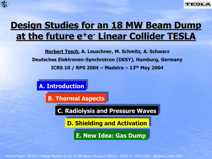
Design Studies for an 18 MW Beam Dump at the future e + e - Linear Collider TESLA. Norbert Tesch , A. Leuschner, M. Schmitz, A. Schwarz Deutsches Elektronen-Synchrotron (DESY), Hamburg, Germany ICRS 10 / RPS 2004 – Madeira – 13 th May 2004. A. Introduction. B. Thermal Aspects.

E N D
Design Studies for an 18 MW Beam Dump at the future e+e- Linear Collider TESLA Norbert Tesch, A. Leuschner, M. Schmitz, A. Schwarz Deutsches Elektronen-Synchrotron (DESY), Hamburg, Germany ICRS 10 / RPS 2004 – Madeira – 13th May 2004 A. Introduction B. Thermal Aspects C. Radiolysis and Pressure Waves D. Shielding and Activation E. New Idea: Gas Dump
A.2 Water Beam Dump • Problem: How to dump 18 MW? Solid, fluid or gas based beam dump? • Solid dump: graphite-copper-water dump with heat conduction from copper to water • Even with a fast sweeping system (needed to distribute the energy) the solid option was not practicable for the given beam power in terms of heat extraction • Therefore the base line design was the fluid (water) dump option ! The basic parameters of the water beam dump • Cylindrical H2O volume with L=10 m, Ø=1.5 m and p=10 bar Tboil=180°C • Fast (within bunch train) circular sweep with Rfast= 8 cm needed to avoid local boiling • Not considered here: beam window (vacuum/water, huge design effort!!!) and beam pipe Problems to be addressed: • Radiation Handling • Shielding • Activation • Dismantling and disposal of activated material@ final shut down Other Processes Radiolysis Pressure waves Thermal Aspects Heat extraction external / internal
A.3 Schematic Layout of Water Beam Dump exhaust / chimney general cooling water sand containment shielding hall air treatment water-system water-dump vessel basin dump shielding commissioning beam spent beam
B.1 External Heat Extraction general cooling water 60°C 30°C Heat Exchanger B Two-loop system with pB pA Static Pressure 10bar 70°C 40°C Main piping DN 350mm Secondary Loop Pump B Water flow of 140 kg/s neededto remove 18 MW 70°C 40°C Heat Exchanger A Static Pressure 10bar 80°C 50°C 1% to 10% of total water flow Recombination system should be directly in return pipe ! Primary Loop 18MW / T=30K 140kg/s Hydrogen Recombiner Water Filtering (ion exchanger, resin filter) Pump A Water Dump 18m3, 10bar Storage Container Scheme of Water System
B.2.1 Internal Heat Extraction - Introduction Heating Process temperature Tinst Teq 1/rep time T0 Tinst :instantaneous temperature rise caused by energy deposition of 1 bunch train, dE/dV(r,z) = c Tinst(r,z), thermal diffusion within 1ms only 10m in water Teq :temperature rise assuming a time independent heat source S, with average power and spatial distribution given by subsequent bunch trains, S(r,z) = 4Hz dE/dV(r,z) conservative estimation for the temperature at a given position ŝ=(r,,z): T(ŝ) T0 +Teq(ŝ) + Tinst(ŝ); with T0 = water inlet temp. (50°C) Task under the given external water mass flow of 140kg/s, create a suitable water velocity field inside the dump vessel, in order to: keep T(ŝ) well below boiling point (180°C) at any position, i.e minimize Teq(ŝ)
B.2.2 Internal Heat Extraction - Heat Source Tinst(r,z) = 1/(c ) dE/dV(r,z) (Tinst)max = 40K @r = 8cm, z 200cm Tinst = 28K @r = 8cm, z 300cm 1 bunch train in water, 6.8 1013 e- @ 400GeV x= y= 0.55mm and fast sweep Rfast= 8cm e- 4Hz bunch train repetition: (dP/dz)max 50kW/cm @ z 300cm dP/(dzdr) dr = 50kW/cm dP/dz dz = 18MW z=300cm radial power density @ z=300cm longitudinal power density
in: 140kg/s, 50°C out: 140kg/s, 80°C 260 kg/s 130kg/s 130kg/s T0=54°C 120kg/s e- 130kg/s 130kg/s 82°C 59°C 10kg/s z=3m B.2.3 Internal Heat Extraction – Fichtner* * calculations done by Fichtner GmbH & Co KG velocity (r, ) [m/s] 2 1 1.5m 0 vortex flow, velocity f(z), CFD-ACE 6.6 code front / rear part split and water mixing internal flow140 to 280 kg/s,here 260 kg/s water velocity at inlet nozzle 30 m/s ! p (in-out) 5 bar 130 kW pump power ! 2d (r, ) stationary simulation at z=3m : T0+max(Teq+Tinst) = 54°C+47K+28K = 125°C well below 180°C boiling point ! T0 + Teq(r, ) @ z=3m [°C] 101 91 81 max(Teq) = 47K 71 61 T0=54
B.2.4 Internal Heat Extraction – Framatome* * calculations done by Framatome ANP GmbH in: =140kg/s, 50°C out: =140kg/s, 80°C velocity (r, z) [m/s] r 125 mm e- v 2.8 – 2.4 m/s z tube 1 tube 2 0 0 50mm 10m T0 + Teq(r, z) longitud./radial flow, 3d, PHOENIX 3.4 code internal flow = external flow =140kg/s tube 1/2: 0.1/0.02% porosity 15% radial flow max. tube 2 temp., 50°C+45K+0K = 95°C max. water temp.between tube 1 & 2 T0+max(Teq+Tinst) = 50°C+58K+0K = 108°C max. tube 1 temp.is at z 4m, r=130mm T0+max(Teq+Tinst) = 50°C+34K+7K = 101°C [°C] tube 2 108 r max(Teq) = 58 K 125mm z 0 3.3m 5m 6.7m tube 1 T0=50
C.1 Pressure Waves - TÜV-Nord* Assumptions r 75cm consider 1 bunch train 860s long as dc-beam source: S = 1/860s dE/dV for 0 t 860s and S = 0 otherwise CFD code Fluent 6.0 without handling of phase transition 10bar, 50°C vsound1.5km/s e- 10m z 400GeV, =0.55mm, 8cm fast sweep p [bar] Results p(r) @ z=2.5m 0 t 800s • in water:pmax 3.7bar near z-axis @ 100s pmin -1.6bar near z-axis @ 950s reduces boiling temp. & solubility of gases !!! • at vessel cylinder: pmax 1.8bar @ 650s • at front/rear face (windows): pmax 0.5bar • pressure wave decay to 0 after 3ms (<<250ms) 3 t [s] 2 600 800 700 500 1 400 300 10 50 100 150 200 0 r [cm] 0 10 20 30 40 50 60 70 75 p [bar] p(r) @ z=2.5m 0.8 t 1.6ms Pressure if close to boiling temperature (imperfect beam with 6mm, no sweep, after 325s) • in water: pmax 9bar, pmin -6bar • at vessel cylinder: pmax 2.7bar • at front/rear face (windows): pmax 0.5bar • pressure wave decay to 0 after 20ms 2 1.2 1 1.1 0.8 1.4 1.3 1.6 0 1.5 1.0 t [ms] 0.9 -1 r [cm] 0.95 75 0 10 20 30 40 50 60 70 * calculations done by TÜV-Nord Gruppe -2
C.2 Radiolysis Fundamentals H2O cracked by shower of high energy primary electron net production rate at 20°C and 10 bar:30 ml/MJ H2and15 ml/MJ O2corresponding to 0.27 g/MJ H2Owith spatial distribution according to dE/dV profile solubility in water at 60°C: H2: 16 ml/l and O2:19.4 ml/l Our Case 18 MW:4.8 g/s H2O cracked whole primary water (30m3) would be radiolysed in 72 days ! recombination needed with 0.54 l/s H2 + 0.27 l/s O2 4.8 g/s H2O + 58 kW (0.3% Pbeam) solubility limit during 1 bunch train at 10 bar dE/dV 530 J/cm3 for H2& dE/dV 1300 J/cm3 for O2; our case (dE/dV)max= 160 J/cm3 So far it looks almost good, BUTH2-control is a critical thing: solubility during bunch train passage can be exceeded locally due tolocal pressure drops with negative p or rise of Tinst danger of H2 gas bubblescomparable to local boiling if not all H2 is recombined, H2can accumulate atspecial locations (local pockets) danger of explosion (e.g. nuclear power plant Brunsbüttel) • recombination in gas-phase without expansion doubtful • recombination should happen directly in return pipe of dump vessel to ensure that 100% of the water will reach the decompress-compress stage Framatome proposal Fichtner proposal
surface 7m sand 3m normal concrete dump 3m normal concrete soil & groundwater D.1 Radiation Handling Shielding of water vessel towards soil, groundwater and surface* soil & groundwater : 3m normal concrete or equivalent to reach planning goal of 30 Sv/a due to incorporation surface: 3m normal concrete or equivalent + 7m sand or equivalent to reach planning goal of 100 Sv/a due to direct radiation * calculations done with FLUKAcode Activation of primary circuit* 18MW, 30m3 water Main contribution of activation in watercomes from 3H and 7Be 3H: 20keV -, t1/2=12a, Asat=250TBq, A(5000h)=8TBq,A(10a)=110TBq - no direct dose rate, but problem if released due to accident or maintenance ! 7Be: 478keV , t1/2=54d, Asat=108TBq, A(5000h)=102TBq - main contributor to local dose rate, assume equal distribution in water system 300mSv/h at surface of component and 50mSv/h in 50cm distance ! (after 5000h) - accumulation in resin filters, but also adsorption on circuit surfaces (esp. heat exchanger) local shielding needed ! 2cm thick stainless steel dump vessel gives400mSv/h on its axis (5000h and 1 month cooling) regular inspection of vessel (welds, ...) seems to be problematic !
exhaust r 5m containment air 5m 5m 2m 2m 2m z 10m 20cm steel + 1.8m concrete dump D.2 Radiation Handling Activation of containment air* 18MW, 3000m3 air necessity of closed containment,„closed“ under-pressure by continuous exchange rate of1vol/h and controlled exhaust looks fine except forshort lived isotopes: need „delay line“ of about 1 hour ! Scheduled opening of primary circuit 30m3 water, 100TBq of 3H flush water into storage tank, 100l remain (0.1mm on 1000m2), vent system with dry gas via 95% efficient condenser 5l 10GBq tritium have to be released to outside air • meeting the limit of 1kBq/m3 needs venting with 107m3 air this takes 1000h=42days with 104 m3/husing a chimney is necessary (acceptance!) Dismantling of activated system after final shut down after 20 years, 200TBq of 3H primary water solidifying as concrete 5000 barrels (200l, 40GBq) steel components (150t, 106Bq/g) & concrete shielding (1500t, 200Bq/g) = a lot of M€ * calculations done with FLUKAcode
E.1 New Idea: Gas Dump Problems and disadvantages of water dump: • High tritium production (to reduce: larger atomic number of dump material) • Critical window design, 10 bar static + 0.5 bar dynamic (reduce pressure) • Radiolysis, local and instantaneous effects represent a severe risk (to avoid: one-atomic gas) • Handling of water during maintenance and final shutdown (less tritium) • Disposal costs not negligible (less tritium) • To overcome most of the problems and disadvantages the following gas beam dump was proposed: • Material: Noble gas (first attempt: Argon @ 1 bar) in inner tube (r=4 cm) acts as scattering target, (energy deposition of 0.5 %) and distributes the beam energy longitudinally (no sweeping) • Main part of the energy is dumped in Iron shell of radius 52 cm (average power loss 18 kW/m) • Surrounded by 4 cm thick Water cooling system • Dump system has diameter of 1.20 m and length of 1000 m • Can be used as- dump as well tunnel gas dump
E.2 Gas Dump: Energy Density Energy density in GeV/cm3 in r-z view for one 400 GeV electron* * calculations done with FLUKAcode
E.3 Gas Dump: Comparison Advantages of gas dump: • Tritium production • Beam window • Radiolysis • Maintenance and disposal • Cases of emergency • Acceptance and permission !!! Disadvantages of gas dump: • Length of dump inside collider tunnel • Space for additional shielding needed adopted tunnel design necessary • Not easy to reach constant energy density of18 kW/m over whole length Conclusion: • The fluid (water) beam dump seems to be feasible, but with severe disadvantages !!! • The gas (argon) beam dump option seems to be a very attractive alternative and will surely be considered in an early design stage of the next linear collider !!!