Download
1 / 23
230 likes | 232 Views
This paper discusses the design, development, and testing of the Level 0 Pixel Trigger System for the ALICE experiment at the LHC. It includes information on the specifications, constraints, and status of the project.

E N D
12th Workshop on Electronics for LHC and Future Experiments • The Level 0 Pixel Trigger System for the ALICE experiment • G. Aglieri Rinella1, A. Kluge1, M. Krivda1,2 • On behalf of the SPD project in the ALICE collaboration • Introduction • Specifications and constraints • System design • Development and testing • Status of the project • 1CERN European Organization for Nuclear Research, Geneva, Switzerland • 2Institute for Experimental Physics, Kosice, Slovakia G. Aglieri Rinella, LECC2006, Valencia
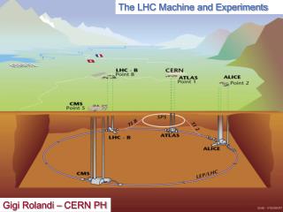
The ALICE experiment • Nucleus-nucleus collisions at the LHC collider: quark-gluon plasma • Research program on p-p interactions • Silicon Pixel Detector (SPD) Interaction point • Inner Tracking System • Silicon Strip Detector • Silicon Drift Detector • Silicon Pixel Detector G. Aglieri Rinella, LECC2006, Valencia
Silicon Pixel Detector • 120 half staves • 2 sensors (160x256 pixels of 425x50 mm2 ) • 10 readout Pixel chips (32x256=8192 channels) • 1 on detector readout Multi Chip Module • 1 data output 800 Mb/s 1310 nm digital optical link (G-Link) More details: oral presentation by M. Krivda, “Alice SPD readout electronics”, this conference, this session Silicon Pixel Detector G-Link channel to control room Readout MCM Half stave 141 mm Sensor Sensor 39 mm 76 mm 400 mm z Pixel chips G. Aglieri Rinella, LECC2006, Valencia
Fast-OR • Fast-OR signals • At least 1 pixel hit out of 8192 in a readout chip • 1200 Fast-OR signals, 10 on each of 120 data links • Low granularity: 1200 equivalent pixels with the size of a chip (~13x13 mm2, pad detector) • Transmitted continuouslyevery 100 ns Silicon Pixel Detector G-Link channel to control room Readout MCM Half stave 141 mm Sensor 1 Sensor 39 mm 76 mm 400 mm z Pixel chips G. Aglieri Rinella, LECC2006, Valencia
SPD Fast-OR Trigger • Use the low granularity (chip level) Fast-OR information as input to the Central Trigger Processor for Level 0 decision • Multiciplity trigger in p-p collisions (ALICE-INT-2005-25) • Centrality trigger and selection of impact parameter in heavy ions collisions) (J. Conrad, “Pixel Fast-OR Progress Report”, 28/11/2005) • Different algorithms proposed (topology and multiplicity) • GLOBAL OR • LAYER • SECTOR • HALF SECTOR • SLIDING WINDOW • VERTEX • OCCUPANCY • Combinational functions of 1200 Fast-OR bits • Implementation in large FPGA G. Aglieri Rinella, LECC2006, Valencia
CTP 30 m = 150 ns Requirements • Requirements • Extract the 1200 Fast-Or signals from the 120 optical data links • Process them • Generate output for the Central Trigger Processor • Support of various trigger algorithms on the same hardware • User definable trigger algorithms and remoteconfiguration and control (control room) • Constraints • Overall process latency: 800 ns (ALICE TDR 010 CERN-LHCC-2003-062) • No interference on the existing data readout chain • System location and space occupation G. Aglieri Rinella, LECC2006, Valencia
What do we need to build ? To DAQ in control room 1200 bits @ 10 MHz Optical splitters Fast-OR extraction Processing CTP 120 G-Link 120 G-Link Pixel Trigger System 800 ns 400 ns 150 ns 250 ns Input bandwidth: 120 • 0.8 Gb/s = 96 Gb/s (120 • 1.6 Gb/s) = 192 Gb/s Output bandwidth: 10 Mb/s G. Aglieri Rinella, LECC2006, Valencia
4 Config/cntrl Config/cntrl System architecture Virtex4 Large I/O Virtex4 To CTP Fast-OR • N • • N • Optical TxRx TTCRx DDL SIU Virtex4 Virtex4 USB JTAG Optical receiver boards (OPTIN) Processing board (BRAIN) 75 ns 100 ns 75 ns 250 ns Large number of simultaneous inputs to the processing FPGA High degree of parallelism: latency constraint Processing time: < 15 ns Limiting factor: data deserialization and extraction G. Aglieri Rinella, LECC2006, Valencia
12 optical fiber inputs Optical receiver modules • Compact multi channel optical receiver modules @ 1310 nm were not found off the shelf • Zarlink provided two prototypes of 12 inputs optical fiber receiver modules operating @ 1310 nm • Significant space saving can be achieved with respect to Small Form Factor standard receivers G. Aglieri Rinella, LECC2006, Valencia
Dtrms≈ 30 ps Optical receiver modules (qualifying) • Experimentally qualified • Sensitivity • Bandwidth (exceeds requirements) • Word Error Rate • The samples fully satisfied the requirements • A set of customized receivers has been ordered BER < 1•10-15 @ -18 dBm G. Aglieri Rinella, LECC2006, Valencia
G-Link deserializers • Fast-OR bits are the payload of the G-Link serial link control words • Deserialization and frame alignment • Three solutions: • Altera Stratix GX • XilinxVirtex 2 Rocket I/O • Dedicated ASIC (Agilent HDMP1034) • Tested: • Altera Stratix GXG-Link deserializer (hardware test) • Virtex 2 Rocket I/Odeserializer (simulation) 10010110 10010110 Opto-Rx12 module, P. Vichoudis S. Reynaud, P. Vichoudis, "A multi-channel optical plug-in module for gigabit data reception", this workshop Realignment and 8B/10B decoding blocks cannot be bypassed !! G. Aglieri Rinella, LECC2006, Valencia
160 mm • Almost a Compact PCI card ! • Dimensions are larger than the IEEE 1386 envelope • 12 layers PCB 84 mm Optical receiver boards - OPTIN Zarlink 12 optical inputs 1 Zarlink Parallel Fiber Optic Module 12 Agilent HDMP 1034 G-Link deserializers 1 Xilinx Virtex 4 FPGA (Fast-Or extraction) HDMP 1034 HDMP 1034 Virtex4 HDMP 1034 HDMP 1034 HDMP 1034 HDMP 1034 • Serves two half sectors (6+6 half staves) • Extracts 10 Fast-OR bits from each link • 120 Fast-OR signals Design and layout PCB prototype production Installation of components Testing Full firmware implementation Production G. Aglieri Rinella, LECC2006, Valencia
Zarlink Virtex4 4 Config/cntrl Config/cntrl Zarlink Virtex4 Signal routing 60 Large I/O Virtex4 To CTP • x 10 • Optical TxRx TTCRx 60 DDL SIU Virtex4 USB JTAG BRAIN OPTIN • Interconnections and routing between OPTIN and BRAIN • Backplane • Flat cables • Daughter cards • Time division multiplexing on 60 lines per OPTIN • Experience with the Router and LinkRx cards of the data readout system (M. Krivda, SPD readout electronics) G. Aglieri Rinella, LECC2006, Valencia
12 4 160 mm Zarlink Zarlink Virtex4 Virtex4 86 mm Zarlink Virtex4 Zarlink Zarlink Virtex4 Virtex4 Processing Board – BRAIN 400 mm • 9U motherboard • Large I/O space FPGA, 1500 pins • 5 OPTIN boards on each side as mezzanine cards • Routing of ~ 1000 lines in the motherboard • 800point to pointimpedance matchedsingle ended lines • Digitally Controlled Impedance • Auxiliary high speed (400 Mbps) optical or LVDS I/O channels • Layout ongoing Large I/O Virtex4 360 mm Optical TxRx TTCRx Virtex4 USB DDL SIU JTAG G. Aglieri Rinella, LECC2006, Valencia
4 Monitoring, control and configuration • Status monitoring and control via Alice Detector Data Link (DDL) • Control FPGA • Status and control registers in each FPGA • Remote hardware reconfiguration (via DDL) to change the processing algorithm • Download firmware in local SRAM memory • Program PROMs via JTAG players • Launch FPGA reconfiguration • Debugging and local access interfaces (USB, JTAG) • Integration of the system in the Alice Detector Control System Large I/O Virtex4 PROM Optical TxRx TTCRx DDL SIU Control FPGA USB BRAIN JTAG G. Aglieri Rinella, LECC2006, Valencia
Power dissipation and cooling • High power density • Thermal verification • FEM simulation with dedicated software • Three resistors model for each device • Board and components thermal conductivity • Forced convection • Partially enclosed rack • Hot spots in acceptable limits Courtesy: Emile Dupont G. Aglieri Rinella, LECC2006, Valencia
Summary • The ALICE Silicon Pixel Detector 1200 Fast-OR signals will be used to generate an input to the CTP for the Level 0 trigger algorithm • The ALICE experiment will be the first LHC experiment to include from startup its own silicon vertex detector in the Level 0 decision • The Alice Pixel Trigger Systemis designed and is being constructed • The Pixel Trigger system: • targets the stringent 800 ns latency constraint • allows for reconfigurable trigger algorithms • is independent from the readout chain • features a modular and upgradeable design: • OPTIN optical receiver mezzanine boards with fiber optic receiver modules and G-Link dedicated ASICs • BRAIN Processing board based on a large logic and I/O space Virtex 4 FPGA G. Aglieri Rinella, LECC2006, Valencia
Spares G. Aglieri Rinella, LECC2006, Valencia
Acknowledgements: I.A. Cali’, E. P. Dupont, F. Formenti, A. Kluge, M. Krivda, G. Stefanini, F. Vasey, P. Vichoudis, References: ALICE collaboration, “ALICE physics Performance Report”, CERN-LHCC-2003-049, J. Phys., G30 (2004) 1517-1763 A. Kluge, “The ALICE Silicon Pixel Detector front-end and readout electronics”, NIM A 560 (2006) 67-70 M. Krivda, “Alice SPD readout electronics”, proceedings of this conference J. Conrad et al., “Minimum Bias Triggers in Proton-Proton collisions with the VZERO and Silicon Pixel Detectors”, ALICE Internal note, ALICE-INT-2005-025, 19/10/2005 G. Aglieri Rinella, LECC2006, Valencia
Signal integrity studies • Signal integrity studies on the communication buses • IBIS models of the Virtex 4 output buffers • Physical parameters of the board striplines G. Aglieri Rinella, LECC2006, Valencia
Radiation effects Neutron max fluence: 2.0 • 108 cm-2 (10 y) Morsch, Pastircak,Radiation in ALICE Detectors and Electronic Racks, ALICE-INT-2002-28 Central Trigger Processor using SRAM based ALTERA Cyclone EP1C20 Radiation Results of the SER Test of Actel, Xilinx and Altera FPGA instances, iROC report, 2004 Failure In Time (FIT): errors in 109 years SEFI: Single Event Functional Interrupt SEU: Single Event Upset (configuration) Errors in 10 years operation G. Aglieri Rinella, LECC2006, Valencia
Trigger latencies and rates G. Aglieri Rinella, LECC2006, Valencia
A. Kluge Time resolution SPD time resolution: 100 ns Pileup of event data in p-p interactions at 25 ns bunch crossing rate G. Aglieri Rinella, LECC2006, Valencia