Download
1 / 15
150 likes | 162 Views
Enhancing Structural Geology Using Mars Data? You Bet!. Eric B. Grosfils Geology Department Pomona College. 50 km. Structural Geology in a Typical Undergraduate Curriculum. Arsia Mons Caldera. PHYSICAL GEOLOGY (INTRO) COURSE

E N D
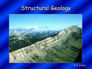
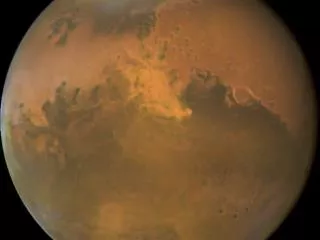
Enhancing Structural Geology Using Mars Data? You Bet! Eric B. Grosfils Geology Department Pomona College
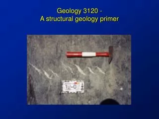
50 km Structural Geology in a Typical Undergraduate Curriculum Arsia Mons Caldera PHYSICAL GEOLOGY (INTRO) COURSE • Basic Styles/Types… folding, faulting, jointing, tilting. Stratigraphy interpretations. • Illustrated by block diagrams, field examples • Opportunities to use Mars examples for illustration and for teaching stratigraphic relationships are abundant! • Mars mission web sites often organize collections of “best images” topically, so tracking down examples is straightforward. http://themis.asu.edu/zoom-20050613A
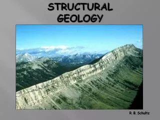
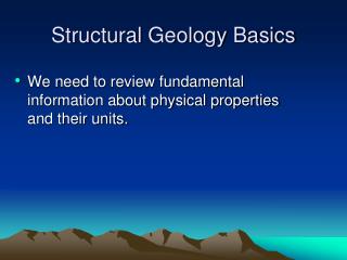
Wrinkle ridge topography and origin 50 km V.E. = 5x Structural Geology in a Typical Undergraduate Curriculum STRUCTURAL GEOLOGY (UPPER LEVEL) • Fundamentals • e.g., force and stress, deformation mechanisms and strain, rheology • Brittle Deformation Processes and Structures • e.g., joints and veins, faults, failure criteria, pore pressure effects • Ductile Deformation and Structures • e.g., folds and fold mechanics, foliations and lineations, ductile shear • Tectonics and Regional Deformation Structural geology is both quantitative and visual – the topic is perfect for integration of available Mars datasets!
Cerberus Fossae • It has been proposed by many researchers that the Cerberus fractures that extend SE from Elysium Mons are underlain by dikes. • Theoretical, experimental and field data indicate that the width of dike-induced fracturing at the surface is ~twice the depth to the top of the dike (cf. Mastin and Pollard, JGR, 1988). • Does the dike hypothesis for the Cerberus Fossa at left pass this test? 5 km http://themis.asu.edu/zoom-20031029a
Cerberus FossaDike Underlain?You test and decide! http://www.nearingzero.net/ Remember The width of dike-induced fracturing at the surface is ~twice the depth to the top of the dike… 5 km http://themis.asu.edu/zoom-20031029a
Cerberus Fossa – Dike Underlain? • Typical fracture width on the plains, ~400 m, suggests depth to dike top is ~200 m • For the topographic peak, 1300 m width suggests that the depth to the dike top is on the order of 650 m • But, need to calculate the height of the topographic peak at the measurement site to complete the test! ~400 m ~1300 m 5 km http://themis.asu.edu/zoom-20031029a
Cerberus Fossa – Dike? Incidence Angle is 76.6° (sun is 13.4° above horizon) Solar Azimuth is 148.6° (measured cw from E, so sun shining toward N58.6E) • Shadow length is ~1900 m at measurement location • From trigonometry, peak is ~450 m tall • Hypothesis passes the test: 200 m (below fracture) + 450 m (height of peak) = 650 m (below peak) x 13.4° 1900 m N58.6E ~1300 m 5 km http://themis.asu.edu/zoom-20031029a
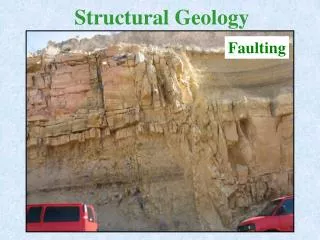
Pit Chain Formation CENTERED PIT 5 km PIT ALONG NORMAL FAULT • In some places on Mars, many grabens have chains of pits centered within them and aggregated along bounding normal faults. • One mechanism proposed for their formation (e.g., Ferrill et al., GSA Today, 2004) is that the pits form when low cohesion surface materials collapse into void spaces created during dilational fault slip. • Such features are not seen all over the place on Earth… why not? • Testing the collapse hypothesis from a structural standpoint and thinking about the Earth-Mars difference promotes analog experiments, Mohr Circle analysis, etc.! “SWALLOW HOLE” http://themis.asu.edu/zoom-20041119a
Pit chain deforming gravels above basalt basement in NE Iceland. Region shown in the air photos is part of the western bounding fault system for a reactivated graben 1 km wide. The event produced 1.5 m of horizontal extension and 1 m of vertical throw. Pits formed are orders of magnitude smaller than on Mars. Figure 5 of Ferrill et al., GSA Today, Oct. 2004. Photo in (A) taken by George McGill 7/3/1976.
Set up an analog models, explore if/how parameters such as thickness of the unconsolidated layer will affect the pit chain geometries produced! Figures 2 and 4 of Ferrill et al., GSA Today, Oct. 2004.
Hoek-Brown Failure envelope for an “average” basalt s1 ≈ 50 MPa 5 km depth, Mars 2 km depth, Earth 156° Figure 6a and 6b of Ferrill et al., GSA Today, Oct. 2004. (c) is derived from Figure 6c of Ferrill et al., 2004. • Mohr circle analysis can be used to explore the conditions consistent with dilational faulting (tensile and hybrid faults, stated by Ferrill et al. to have fault dips for basalt >78°). • For the Earth, such faults will occur in upper 2 km or so (under lithostatic loading), but pits formed are readily eroded (i.e., by stream in Iceland example) and don’t survive very long. • On Mars, lower gravity means that dilational faulting can occur in upper 5 km or so. Larger pits may form due to thickness of low-cohesion surface layer (test with analog model!), greater depth extent of dilation, less rapid erosion, and net accumulation of dilation volume via multiple fault reactivations. • One could go on to calculate (a) the amount of dilation required to account for drained volumes, (b) how these dilations compare with the fault dips/offsets observed to test for consistency…
Calculate strain using impact crater deformation! ( But beware of oblique impacts… ) Galle “Happy Face” Crater in Yellow (51.1°S, 31.3°W; 215 km across) Elliptical (Strained?) Crater in Blue to NE
5 km 5 km Canyonlands National Park DEM Arcuate FaultSystems? http://www.mines.edu/academic/geology/faculty/btrudgil/research.html Rotated Fault Blocks? http://themis.asu.edu/zoom-20050324a http://www.geosci.usyd.edu.au/users/prey/Teaching/Geol-1002/HTML.Lect6/sld010.htm
A Few Other Seed Ideas… • Fault Length-Displacement Analyses (cf. papers by R.A. Schultz & colleagues) • Regional Strain Calculations Using Fault Displacement Measurements • Analysis of Joints/Fractures Seen in MER Images • Constraining Wrinkle Ridge Origin Using Topography • Fault-bend folds? (cf. work by Okubo & colleagues; by Golombek & colleagues) • Fault-propagation folding? (investigate using PC/MAC freeware written by Allmendinger?) • Thin- or thick-skinned deformation? • Graben/Rift Topo - purely tectonic? (cf. papers by Rubin ; Schultz; Goudy) • Polygonal Fracturing -- constrain thickness and type of material in the northern plains (Utopia Basin) burying old impact craters and forming drape folds (cf. papers by Buczkowski & colleagues)
Now, What Are You Going to Try? http://marsrovers.jpl.nasa.gov/gallery/press/opportunity/20060307a/Sol744B_P2351_L257F-B744R1.jpg