Download
1 / 21
210 likes | 336 Views
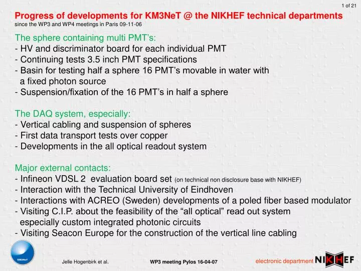
Progress of developments for KM3NeT @ the NIKHEF technical departments since the WP3 and WP4 meetings in Paris 09-11-06. The sphere containing multi PMT’s: HV and discriminator board for each individual PMT Continuing tests 3.5 inch PMT specifications

E N D
Progress of developments for KM3NeT @ the NIKHEF technical departments since the WP3 and WP4 meetings in Paris 09-11-06 • The sphere containing multi PMT’s: • HV and discriminator board for each individual PMT • Continuing tests 3.5 inch PMT specifications • Basin for testing half a sphere 16 PMT’s movable in water with a fixed photon source • - Suspension/fixation of the 16 PMT’s in half a sphere • The DAQ system, especially: • Vertical cabling and suspension of spheres • First data transport tests over copper • Developments in the all optical readout system • Major external contacts: • - Infineon VDSL 2 evaluation board set (on technical non disclosure base with NIKHEF) • - Interaction with the Technical University of Eindhoven • - Interactions with ACREO (Sweden) developments of a poled fiber based modulator • - Visiting C.I.P. about the feasibility of the “all optical” read out system especially custom integrated photonic circuits • Visiting Seacon Europe for the construction of the vertical line cabling
General KM3NeT data communication requirements ? PMT data from sphere to shore (10 Gb/sec) Detector control data from shore to sphere v.v. (100 Mb/sec??) compass, tilt, temperature, flow, salinity, acoustics, beacons ?? Communication for time calibration Determine a different physical layer for emergency reset, a fallback channel, redundant control??
Many variations of the booming FTTH architecture C.I.P. Is a partner in European research programs on WDM-PON e.g. PIEMAN ~ Photonic Integrated Extended Metro and Access Network low cost reliable
General diagram photonic-copper mix m branches c 48V/3.5 logic PMT l1.. ln GPS rec. laser OM 1 l1..n 1 .. 32 x clck-sc-cal. c PMT 1:n vdsl2 Clock Logics <100Mbps apd l1 OM 2..30 data Vertical Cable VDSL2 apd ln CPUs GbE Copper branch equivalent 10kV Power vdsl2 vdsl2 vdsl2 Shore station mux 400/48V 30:1 logic apd Maincable Branch cable: n x l in one fibre, 1 x 10kV power line l1 Main cable: m fibres, 1 x 10kV power line n = number of lines on 10kV branch (<60) LINE 1 m = number of branches 3Gbps Anchors LINE 2..n ADM 10kV/400V Ref: Catania JB l1.. ln l2.. ln branch
Infineon VDSL2 evaluation boards 540 meter twisted pair 18 x 30 meter VDSL 2 CO (central office) VDSL 2 CPE (customer premises equipment)
First VDSL 2 channel measurement amplitude time 4096 carriers power frequency
General diagram “all optical” Shore station GPS rec. laser Single Fibre per line l1..n clck-sc-cal. Logics Clock cal apd l2 ½ns ~16 x data Clock apd ln+1 Optical module CPUs GbE Copper c serdes PMT Power 1 .. 16 x c l1>l2 PMT data Production model Independent manufacturing 365 lines? Power ~30 x l1+l2 ln+ln+1
Progress on the general diagram “all optical” Distributed modules offshore Concentrated equipment on shore Suits well in the base line approach: Cost driven, Proven technology Shore station GPS rec. laser l1..n clck-sc-cal. Logics Clock cal Optical module or instrumentation apd Single Fibre per line ? 200 optical channels in 1 fibre possible l2 ½ns ~16 x data Clock apd process O/E ln+1 CPUs GbE Copper c serdes PMT 1 .. 16 x SOA c Power PMT EAM data l1 or l1 + l2 Power Production model Independent manufacturing 365 lines? ~25 x ln+ln+1 Line base
PMT outputs of a typical event in a multiple PMT OM ~ 7ns Time over threshold single photon pulse resourced by a 3.5 “ PMT 0 7 Hit 1 Late hit? 8 Hit 2 9 PMT number Two with overlap 10 Shower? 11 Random or first? 12 15 7 nsec time 1 nsec Single photon pulse : Typ 5 nsec (Min 2 nsec and 7 nsec post ampl.)
Electronic-photonic front end e.g. every 2 nsec CW + clk pulse from shore one optical pulse triggers the intrinsic part of the photo diode Puls det& gain flattening electric output to optical modulator Modulator, e/o and 2R or 3R ? unit D D D D D D D D D D D 15 5 4 3 1 0 2 I0 I1 Ix identifier 16 PMT’s and 4 identifiers => 20 data bits. Optical trigger repetition rate: 1,6 nsec <=> 3,2 nsec 80 <=> 160 psec sample pulse width. If “D” delay 100 psec then the system adapts to10Gbit/secoptical transmission technology. I0 I1 Ix 15 5 4 3 2 1 0 serialized output after one optical trigger ~ 7ns 1,6 nsec <=> 3,2 nsec From PMT’s
PMT value readout method “all optical” Late hit? Hit 1 PMT 2 Hit 2 PMT 5 Readout pulses x + . . . 1 2 3 4 5 6 7 8 1 2 nsec 2 3 Readout pulses 4 5 PMT 1 2 3 4 5 . . . . . . 100 psec
Single Serial to parallel photonic chip (metal-silicon-metal photo diode) e.g. signal from PMT circuitry Optical trigger 100 psec
Basic approach “head end” e/o readout clk 1,6 <=> 3,2 nsec Propagation Cal. pulse o/e Trigg. TDC Calibration pulse enable Clk gen. event time timestamp generation de_serialize GPS line control event Data buffer data Computer system zero supp . ? The shore station transmits a calibration signal. The calibration signal is reflected by each optical module to the shore station for signal propagation delay calculation.
Up to optical system simulation Eye pattern time jitter noise jitter Characterizing: Rise times Fall times Jitter at the middle of the crossing point of the eye overshoot And many other numerical descriptions in order to compare devices. BER: Bit Error Ratio or Bit Error Rate the ratio of the number of bits received erroneously to the total number of bits transmitted. BER is limited by random noise and/or random jitter and is a statistical value More detail: www. maxim-ic.com , app note: HFTA-010.0: Physical layer performance: testing bit error performance Examples: 10 Gb/sec transmission requirements specify a BER better than 10-12
simulation setup for fibre specification Scoop, visualizer Standard fibre types: SMF 128 dispersion 0 @ 1310 nm SMF 652 B dispersion 0 @ 1310 nm G 655 reduced dispersion @ 1550 nm • CD chromatic dispersion • PMD polarization mode dispersion • Length 100km • Attenuation 0.2 db/km • Wavelength nom. 1550 nm • Bit rate 10 Gb/sec VIPsystems (virtual photonics industries)
Optical output @ EAM => input for the fibre types to be simulated eye pattern and BER contour Highest BER 10-4 Lowest BER 10-30
SMF 128 CD: 16.10-6 s/m2 (real world 16 ps/nm.km) eye pattern and BER contour Highest BER 10-4 Lowest BER 10-5
Antares / Nemo fibre G655 with CD: -3.1 10-6 s/m2 eye pattern and BER contour Highest BER 10-4 Lowest BER 10-30
Antares fibre G 655 with PMD =< 0.08 ps/km-1/2 en CD: -3.1 ps/nmkm eye pattern and BER contour Highest BER 10-4 Lowest BER 10-16
KM3NeT DAQ vertical cabling solutions In relation with today's developments for fibre to the curb or fibre to the home FTTx All copper in detector strings (risers) Event time stamp locally at each detector floor Moderate high speed data communication Enlarged local electronics off shore Store and forward data communication Joined power and data transport All fibre in detector strings (risers) Event time stamp on shore Very high speed data communication minimized local electronics off shore Real time data communication (optical channels) Power and data transport separated Fibre network for data communication over a long distance based on optical channels includes “optical addressing”
Prospects All copper in detector strings (risers) Event time stamp locally at each detector floor Moderate high speed data communication More local electronics off shore Store and forward data communication Power and data can be transport united All fibre in detector strings (risers) Event time stamp on shore Very high speed data communication Less local electronics off shore Real time data communication (optical channels) Power and data transport separated • Costs relay on: • primary hardware • power needs • reliability • open system • construction • test benches • deployment • ease of mass production