Download
1 / 56
590 likes | 804 Views
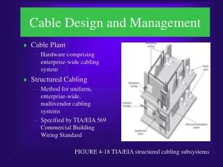
Interconnect Cable Design and Assembly. The Ideal Interconnect Cable Assembly. For High Performance I/O Applications. Fault Free: Form, Fit and Function 100% Electrical Continuity Corrosion-Resistant Materials Maximum Flexibility and Durability Minimum Size and Weight

E N D
The Ideal Interconnect Cable Assembly For High Performance I/O Applications • Fault Free: Form, Fit and Function • 100% Electrical Continuity • Corrosion-Resistant Materials • Maximum Flexibility and Durability • Minimum Size and Weight • Abrasion-Proof Coverings • Crush-Proof Conduit • Hi-Rel Crimp Contact Connectors • Precision, Gold Plated Contacts • Harsh Environmental Protection • EMI Immunity
The Compromise • “Acceptable” Performance and Cost Dictate Design • Fit and forget vs. frequent mating cycles • Exposed environmental vs. enclosed mounting • Commercial vs. military • High power vs. signal (or combined) • Crimp vs. solder • Shielded vs. unshielded
Factors That Impact Cable Design and Construction:(1) Environmental and Mechanical • Fluid Immersion • Chemical Resistance • Abrasion • Clamping • Flame/outgassing • Corrosion • Impact/crush • Shock and Vibration • Temperature Cycling • Altitude • Fungus • Pressure Extremes • Pull Forces/Elongation • Bend Radius • Aging • Strain-Relief
Factors That Impact Cable Design and Construction:(2) Electrical • Current rating • Wire voltage rating • Wire AWG and Number • Wire material/finish • Insulation/dielectric • EMI/EMP • Impedance requirement • 100 ohm pairs (Ethernet) • 90 ohm pairs (USB) • 75 ohm coax • 50 ohm coax
Factors That Impact Cable Design and Construction:(3) Usability and Ergonomics Size, Weight, Flexibility, Routing, Cable Management
Interconnect Cable/Conduit Design, Materials and Construction
Connectorized System-to-System I/O Cabling From One Box to Another Box
Feed-Thru Cabling For Non- or Partially-Connectorized Applications
(Non-Connector) Feed-Through Accessories • Complete range of functional types: shield termination, strain-relief, environmental sealing etc. • Split shells enable easy assembly and maintenance at any stage in the project.
Open Wire Bundle Cables Lightweight and Flexible Cable Harnesses • Appropriate where no noise or crosstalk from adjacent wires is expected • Prevalent for data transfer with tightly twisted pairs • Shielded pairs might be inside of an unshielded cable assembly • Great for routing
Open Wire Bundle Cables Used in Internal Box Wiring and Other Enclosed Non-Environmental Systems • Low cost compared to overmolded or jacketed solutions • Field repairable • Non-Environmental • Not particularly durable
Management of Open Wire Bundles • Split tubing • Expando braid • Broom Stitch • Others • Wraps/tapes • Cable ties • Cable clips • Spiral Wrap
Standard Jacketed/Shielded Cables Backshell Equipped for External Harsh Environments • Shields added to twisted pairs, or multi-conductor cables, to help prevent EMI (victim or source). • Jacketing extruded, shrunk on or blown on • Types of jacketing based on environmental conditions such as immersion, chemical or caustic fluid exposure, corrosion potential, temperature or radiation exposure. • Field maintainable, user installable backshells
Jacketing Styles Wide Range of Choices to Meet Every Need • Extruded jacketing is the best environmental sealing option • Blown on jacketing—soft rubber tubing is overfilled with compressed air, cable inserted, and tubing allowed to collapse for sealing fit • Both options offer a wide range of material types. • Heat-shrink tubing is inexpensive, lightweight and ideal for short runs and prototypes
Environmental Sealing for Jacketed Cables Typical exploded view of cable sealing backshell
Shield Termination Options for Jacketed/Shielded Cables Dozens of different styles • Conical ring backshells • Tag ring backshells • Cable Sealing Band in a Can Backshells • Tinel-Lock Backshells • Sealtite/Liquidtite Conduit Backshells • Band-It Clamping System • Conductive epoxy potting for EMI shielding and grounding in tight space applications
Jacketed/Sealed Cable Applications External Wiring Requirements Battlefield electronics Under vehicles Long cable runs connecting field equipment Soldier systems
Overmolded Sealed Cables Ultimate Environmental Protection • Use of encapsulating plastic medium to cover backshells, adapters and transitions • Effectively isolates conductors from contamination and protects from abrasion • Mold geometries for unique applications • Can integrate mounting brackets and other hardware right on to the cable assembly • Tamper resistant
The Advantage of Overmolding • Outstanding environmental protection for harsh and caustic environments compared to unjacketed solutions • Polyurethane, Viton, EPDM, Polyamide and Glenair proprietary materials provide robust protection for connectors and cables in harsh/caustic environments • Injection molding/transfer molding is a simple, reasonably priced solution to physical protection • Design flexibility: from simple point to point, to complex multiple branch assemblies—even fiber-optic and hybrid electrical/optical designs
Top Ten Overmolding Bullet Points Superior, water-proof environmental sealing Robust mechanical protection of the connector Superior mechanical/strain-relief protection of wire/contact terminations. Superior resistance to chemical exposure damage. No induced cold flow stress to wire insulation or terminations compared to cable clamps Superior electrical isolation and insulation Reduced exposure of metal parts to wear damage Flexible routing/cable entry angles Superior performance compared to boots and backshells Tamper proof
Old School Overmold Tooling • Manual injection tooling serves a broad range of standard connectors. • Provides savings to customers and faster time to market. • All classes of rectangular connectors • Mil-Spec and commercial cylindrical
Production Overmold Systems • Numerous other materials, besides Viton, are suitable for injection molded protection of connectors and terminations. • Polyamide provides “good” levels of solvent resistant, abrasion resistance and temperature tolerance compared to Viton • New equipment and production system adds speed and reliability to catalog point-to-point or pigtail assemblies for the Series 80 “Mighty Mouse”.
Backshell Devices Used in Overmolding • Banding backshells, used for shield termination and the attachment of heat shrink boots are also employed in Overmolding. • The parts are blast abraded to facilitate overmold material bonding. • Design shown at right incorporates a threaded section for easy repair and maintenance or terminations.
Overmolded Cable Applications • Preferred technology for fuel cells • Advanced F-18 E/F Fuel Cell Assembly with integral fiber optic media • F-22 Overmolded Fuel Cell Assembly and Wheel Well Assemblies • V-22 Fuel Cell Assembly
Cable Routing and Packaging Capabilities • Essentially unlimited range of breakouts and layouts • Straight, 90 and 45 degree angular specifications. • Existing tooling for many common molding adapters and connectors. • Breakout, bulkhead and transition tooling for many configurations
Imbedding PCB’s with Overmolding • A Unique Application of Injection Overmolding
Overbraid and Tubular Fabric Braid Strength Plus Chemical and Abrasion Resistance • Fabric braid for improved cosmetics, wire management, tensile strength, chemical resistance, abrasion resistance, and flammability reduction
Low-End Tubular Fabric Braid Products • Polyethylene -54°C to +121°C used for abrasion, cut through and overall protection also very flexible. • Polyethylene is very standard and used extensively. • Halar (E-CTFE) -73°C to +150°C provides higher temperature and better mechanical toughness. • Materials are quite common and highly competitive with “Expando” braid type products.
Less Common Non-Metal Braid Products • PEEK 220°C High temp, high performance • Teflon (FEP) 200°C chemical and fluid resistant • Kevlar Extremely tough • Dacron (Polyester) 150°C • Nomex
Overbraid and Tubular Fabric Braid For mechanical protection and EMI applications • Electrical Continuity of a cable or EMI/RFI shielding is the primary purpose but strain relief, cable strengthening and armoring are also provided. • Used for EMI/RFI shielding to prevent “conducted” signals from interfering with sensitive electronics; and to keep intended electrical signals and power from “radiating” and affecting adjacent cables or devices. • Standard braiding materials include bare copper, tinplated copper-covered steel, copper plated with tin, nickel or silver; bronze, stainless steel, copper-covered steel, aluminum wire
Overbraid and Tubular Fabric Braid Mechanical Strength and EMI Protection • Metal braiding physically protects cable conductors while adding tensile strength and integrity to the assembly. • Metallic braids shield cable conductors from line-of-sight EMI penetration or escape, and by taking EMI to ground. • Bulk braid size range from 1/32” to 2-1/2” • Overbraids up to 3” diameter • More than 50 braiders
Ultra-Lightweigth Composite RFI/EMI Braided Shielding • Nickel Plated AmberStrand Composite Shielding Offers Unique Solution to Electromagnetic Compatibility • Expandable, flexible, high-strength, conductive, elastic composite material • Provides abrasion resistance and EMI shielding at a fraction of the weight of metal braid
Foil Shield/Tape Wrap • Lighter Weight and Less Costly Than Braid • Foil shields: aluminum foil laminated to a Mylar, polyester or polypropylene film. • Film gives the shield mechanical strength and added insulation. • Provides 100% electrostatic shield protection. • Can shield individual pairs of multi-pair cables to reduce crosstalk.
Foil Shield/Tape Wrap • Lighter Weight and Less Costly Than Braid • Lighter weight, bulk and less costly than spiral or braid shields and are generally more effective than braid shields in RF ranges. • Foil shields are often more flexible than braid but have a shorter flex life than spiral or braid. • Drain wires often used with foil shields to make termination easier and to ground electrostatic discharges.
Multi-Conductor Cables • Critical element of the harness assembly • Customer defined: • Dimensions • Core Type • Insulation • Conductor, shielding and jacketing • RoHS, UL or other • Electrical (Voltage, etc) • Flame rating • Temperature rating
Coil Cables Common Choice for Telephone/Communication Cables • Specified by “working length,” and “Retracted Length.” • Other design variables include: • Hand pulled or machine pulled • Coil “memory” strength • Orientation and length of straight ends
Summary: Application Checklist for Cable and Harness Specification
Application Checklist: Step One: Working Environment Required Information for Fast Design and Delivery • Shipboard • Aircraft • Secure Communications • Ground Support • Rail/Mass Transit • Space • Missile Defense • Telecommunications • Armored Vehicle
Application Checklist: Step Two: Electrical/Optical Requirements Required Information for Fast Design and Delivery • Application defined requirements for cable performance may include: • Current rating • Test voltage • Insulation resistance • DWV • Signal leakage • Attenuation • Voltage drop • Capacitance
Application Checklist: Step Three: EMI Shielding Requirements Required Information for Fast Design and Delivery • Customer defined shielding specifications for the cable may include: • Shielding effectiveness (dB) • Frequency Range (Hertz) • EMP • TEMPEST
Application Checklist: Step Four: Key Environmental Requirements Required Information for Fast Design and Delivery • Customer environmental requirements for the cable may include: • Moisture/chemical Protection • Low Smoke/Zero Halogen • UL94-V0 Flammability • NBC/CBRNE Resistance • UV Resistance • Temperature Resistance • Controlling Specification
Application Checklist: Step Five: Key Mechanical Requirements Required Information for Fast Design and Delivery • Customer mechanical specifications for the cable may include: • Field Reparability • Crush/Abrasion Resistance • Pull (Tensile) Strength • Flexibility/Flex Cycles • Minimum bend radius • Workmanship standards • Strain-relief
Application Checklist: Step Six: Packaging Required Information for Fast Design and Delivery • Customer packaging/construction requirements for the cable may include: • Critical dimensions/tolerances • Required tooling, such as crimp dies, molds and test fixtures • Specific cable management and identification choices • Approved jacket, boot and dielectric materials • Jacket finish • Specifications on length of lay in twisted pairs or other cable construction details
ISO 9001:2008 and AS 9100:2009 Rev C Certified • Cable Assembly Factories 100% Vertically Integrated • All Key Processes Under Glenair Control • ISO 9001:2000 Certified • AS9100:2004 Rev. B Certified • Certified soldering (NASA STD 8739.3) • Source inspection available