Download
1 / 27
270 likes | 345 Views
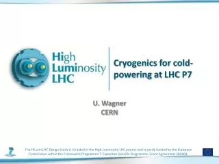
Cryogenics for the cold powering system. U. Wagner CERN. Content. Introduction Study objectives. Overall time frame. Speed study What defines the cooling? Next steps Listing some obvious questions. Trying to establish and order of importance. Conclusion. Work package 6 / Task 6.2 .

E N D
Cryogenics for thecold powering system U. Wagner CERN
Content • Introduction • Study objectives. • Overall time frame. • Speed study • What defines the cooling? • Next steps • Listing some obvious questions. • Trying to establish and order of importance. • Conclusion 1st HiLumi LHC / LARP
Work package 6 / Task 6.2 • Task 6.2. LHC Cryogenics: Cooling and Operation • Study different cooling options within the LHC cryogenic system • Elaborate optimized flow-scheme • Identify and define requirements and components for cryogenic operation and protection • Study space requirements for integration of cryogenic components 1st HiLumi LHC / LARP
Cold powering systems Overview of time scale and location • ≥ 2018 • LHC Points 1 and 5 • Replacement of ARC current feed boxes from LHC tunnel to surface building. • ~ 220 kA total current; ~ 400 m SC link line incl. ~100 m vertical shaft. • LHC point 7 • Replacement of ARC current feed boxes from LHC tunnel to distant underground cavern. • ~ 32 kA total current; ~ 500 m “semi horizontal” SC link line. 1st HiLumi LHC / LARP
Cold powering systems Overview of time scale and location • ≥ 2020 “High luminosity upgrade” • LHC Points 1 and 5 • Replacement of “inner triplet” (IT) current feed boxes from LHC tunnel to surface building. • ~ 40 kA total current; ~ 400 m SC link line incl. ~100 m vertical shaft. • Together with refrigerator upgrade for IT cooling • Integrate solutions for 2018 into refrigerator upgrade • For the time being: • Concentrate on 2018 upgrade and its integration into the existing cryogenic architecture. 1st HiLumi LHC / LARP
General remark Helium property regions for SC link cooling HTS link to be cooled by cold gas No cooling by supercritical helium ! Cooling for HTS Area to avoid Cooling for LTS Preferred: cooling at low pressure No two-phase cooling in extended line structures 1st HiLumi LHC / LARP
Current status Schematic 1st HiLumi LHC / LARP
Future status Schematic Assumptions taken; to be revised by study. 1st HiLumi LHC / LARP
Actual integration of current feed boxes 1st HiLumi LHC / LARP
Assumptions To be verified • Link SC is MgB2 • Splice LTS to MgB2 • Assumed: requires liquid helium bath. • Max MgB2 temperature at current lead connection • Assumed: 20 K • Assumed: max. helium temperature 17 K • Helium consumption for current lead cooling • Assumed 0.05 to 0.06 g/s kA (see next slide) 1st HiLumi LHC / LARP
Helium consumption ofcompound current lead Helium consumption for gas cooled HTS current leads From: HTS current leads: Performance overview in different operation modes A. Ballarino; 2006 1st HiLumi LHC / LARP
Constraints Available cryogenic infrastructure • No available cryogenic infrastructure at new current feed box locations • Maximum envisaged for the time being at surface:LN2 tanks, if necessary. • Maximum envisaged for the time being underground:Nothing. • Cooling supplied from the LHC tunnel • Helium gas recovery at ambient temperature, ~ 1.2 bar. 1st HiLumi LHC / LARP
Transfer line options • Transfer line heat loadsTwo “option classes” • “Nexans like” (semi rigid) transfer line • Cold part: ~0.3 W/m • Shield part: ~2.5 W/m • Custom build, rigid transfer line • Cold part: ~0.04 W/m • Shield part: ~ 1.5 W/m • Not to forget: • Heat loads depend on pipe diameter and fluid temperature 1st HiLumi LHC / LARP
Basic figures • Helium enthalpy change • Vapour at 1.3 bar to 17K, 1.2 bar: 72.2 [J/g] • Assumed current lead consumption • 0.06 g/s kA • Total current in feed box • Pt 1 and Pt 5: ~220 kA (high current case) • Pt 7: ~ 38 kA (low current case) 1st HiLumi LHC / LARP
Upgraded status Schematic SC cooling flow: mSC T max: 17 K Shield flow: mshield Heat load on SC link: QSC 1st HiLumi LHC / LARP
Basic consideration 1 For high current at Pt 1 and Pt 5 • SC cooling flow defined by current lead flow(no shield flow) • msc = 220 kA * 0.06 g/s kA; msc = 13.2 g/s • Max. heat load on SC link:Qsc = 13.2 g/s * 72.2 J/g; Qsc = 960 W • Distributed heat load on SC link: • qsc = 960 W / 400 m; qsc = 2.4 W/m • A distributed load of 2.4 W/m is in the reach of a non-shielded transfer line. • Thermal shielding of current feed box not included. 1st HiLumi LHC / LARP
Basic consideration 1 For low current at Pt 7 • SC cooling flow defined by current lead flow(no shield flow) • msc = 32 kA * 0.06 g/s kA; msc = 1.92 g/s • Max. heat load on SC link:Qsc = 1.92 g/s * 72.2 J/g; Qsc = 139 W • Distributed heat load on SC link: • qsc = 139 W / 500 m; qsc = 0.28 W/m • A distributed load of 0.28 W/m requires a shielded transfer line. • The shield cooling flow is in this example not used for CL cooling. 1st HiLumi LHC / LARP
Basic consideration 2 For high current at Pt 1 and Pt 5 • SC cooling flow defined by heat load on SC link line • “Nexans” line; qsc = 0.3 W/m; qshield = 2.5 W/m • msc = 0.3 W/m * 400 m / 72.2 J/g; msc = 1.66 g/s • Shield flow defined by: lead flow – SC flow • mshield = mlead – msc; mshield = 11.5 g/s • Shield outlet temperature defined by heat load • dhshield = 2.5 W/m * 400 m / 11.5 g/s; dhshield = 87 J/g • Tshield_out = 36.6 K (20 K inlet assumed) • The current lead can be cooled by the mixed flows for SC cooling and shield. 1st HiLumi LHC / LARP
Solution anticipated by A. B. 1st HiLumi LHC / LARP
Basic consideration 2 For low current at Pt 7 • SC cooling flow defined by heat load on SC link line • Rigid line; qsc = 0.04 W/m; qshield = 1.5 W/m • msc = 0.04 W/m * 500 m / 72.2 J/g; msc = 0.28 g/s • Shield flow defined by: lead flow – SC flow • mshield = mlead – msc; mshield = 1.64 g/s • Shield outlet temperature defined by heat load • dhshield = 1.5 W/m * 500 m / 1.64 g/s; dhshield = 457 J/g • Tshield_out = 108 K (too high for lead cooling) • Cooling flow not defined by current lead cooling but by TL heat leak. 1st HiLumi LHC / LARP
Speed study conclusion A: for high current case Pt1 and Pt5 • High current case • The current lead flow is the defining figure. • Heat load on transfer lines of second order. • Invest design effort to obtain a current lead with low coolant consumption 1st HiLumi LHC / LARP
Speed study conclusion B: for low current case Pt7 • Low current case • Heat load on transfer lines defines the cooling flow. • Flow in excess of current lead flow is “wasted” • or • Use a more complex transfer line, using the 60 K, 18 bar flow and feeding this back cold to the LHC distribution. • Invest design effort to obtain a better adapted transfer line. • But: • For the case of “waste”: low charge, low waste. 1st HiLumi LHC / LARP
Task 6.2. LHC Cryogenics: Cooling and Operation • Study different cooling options within the LHC cryogenic system • Elaborate optimized flow-scheme • Identify and define requirements and components for cryogenic operation and protection • Study space requirements for integration of cryogenic components 1st HiLumi LHC / LARP
Urgent study objects • Are the assumptions correct • Which SC for the link line? • MgB2 ? Are there other options? • Max. helium temperature at cold current lead connection. • 17 K ? Depends on SC for link. • What performance in g/s kA can we expect from the future current leads? • Important for “high current” case. 1st HiLumi LHC / LARP
Second step objects • For “low current”, high coolant flow case. • How can we improve on the transfer line side? • Can we connect the SC for the link directly to a copper lead? 1st HiLumi LHC / LARP
Third step objects • System considerations • How to integrate the future current leads into a current feed box? • Do we need to shield the relocated current feed boxes. • How does an actively cooled shield translate to helium consumption? 1st HiLumi LHC / LARP
Conclusions • A basic solution for the cooling is quickly at hand • At closer scrutiny lots of details require clarification. • The interfaces are “interdependent” i.e. we will need to mutually adapt depending on the advancement of the different project parts. • Define common baseline; adapt as we proceed. • Good to see you here ! • Lets start to discuss. 1st HiLumi LHC / LARP