Download
1 / 50
520 likes | 711 Views
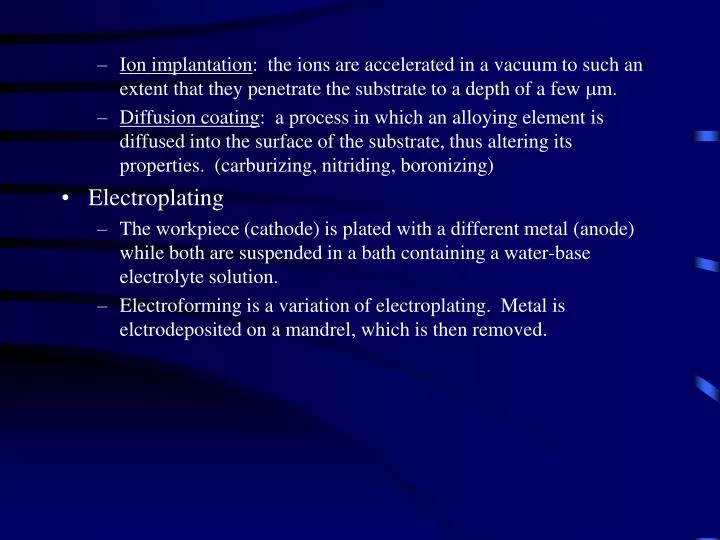
Ion implantation : the ions are accelerated in a vacuum to such an extent that they penetrate the substrate to a depth of a few m m.

E N D
Ion implantation: the ions are accelerated in a vacuum to such an extent that they penetrate the substrate to a depth of a few mm. • Diffusion coating: a process in which an alloying element is diffused into the surface of the substrate, thus altering its properties. (carburizing, nitriding, boronizing) • Electroplating • The workpiece (cathode) is plated with a different metal (anode) while both are suspended in a bath containing a water-base electrolyte solution. • Electroforming is a variation of electroplating. Metal is elctrodeposited on a mandrel, which is then removed.
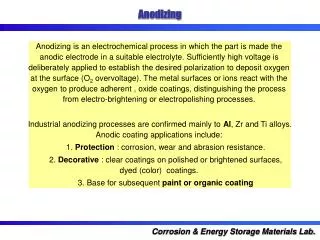
Anodizing • the workpiece is the anode in an electrolytic cell immersed in an acid bath, resulting in chemical adsorption of oxygen from the bath. The workpiece surface is covered with a hard and porous oxide layer. • Applications: aluminum furniture and utensils, architectural shapes, automobile trim, picture frames, keys, sporting goods • Diamond coating of metals, glass, ceramics, and plastics, uses chemical and plasma-assisted vapor deposition process and ion beam enhanced deposition techniques. • Production of free-standing diamond films on the order of 1 mm thick and up to 5” in diameter • properties of diamond: hardness, wear resistance, high thermal conductivity, and transparency to ultraviolet light and microwave frequencies • Used for scratchproof windows, sunglasses, cutting tools, calipers, surgical knives, razors, electronic and infrared heat sinkers and sensors, light emitting diodes, turbine blades, and fuel injection nozzles.
Cleaning surfaces • Cleaning involves removal of solid, semisolid, or liquid contaminants from a surface. • Two types of cleaning methods • Mechanical - physically disturbing the contaminants, as with wire or fiber brushing, dry or wet abrasive blasting, tumbling, and stream jet. • Chemical - usually involves the removal of oil and grease from surfaces. It consists of one or more of the following processes: • solution - the soil dissolves in the cleaning solution • saponification - a chemical reaction that converts animal or vegetable oils into a soap that is soluble in water • emulsification - the cleaning solution reacts with the soil or lubricant deposits and forms an emulsion. The soil and the emulsifier then become suspended in the emulsion
dispersion - the concentration of soil on the surface is decreased by surface-active materials in the cleaning solution • aggregation - lubricants are removed from the surface by various agents in the cleaner and collect as large dirt particles. • Some common cleaning fluids are used in conjunction with electrochemical processes for more effective cleaning. These fluids include: alkaline solutions, emulsions, solvents, hot vapors, acids, salts, and organic compound mixtures. • Cleaning discrete parts having complex shapes can be difficult. Design engineers should be aware of this difficulty and provide alternative designs, such as avoiding deep blind holes or making several smaller components instead of one large component that may be difficult to clean, and provide appropriate drain holes in the part to be cleaned.
Engineered Metrology and Instrumentation • Engineering metrology is defined as the measurement of dimensions • postprocess inspection • in-process, online, real-time inspection • Dimensional tolerances - the permissible variation in the dimensions of a part
Instruments • Line-graduated (marked) • steel rule, bar, or tape (1 mm or 1/64 in.) • vernier caliper or caliper gage (25 mm or 0.001 in.) • micrometer (2.5 mm or 0.0001) used for measuring the thickness, and inside or outside diameters • diffraction grating • telescoping gage for indirect measurement of holes or cavities • bevel protractor to measure angles • Comparative length-measuring instruments • Amplifies and measures variations or deviations in distance between two or more surfaces • dial indicators (1 mm or 40 min) • electronic gages sense the movement of the contacting pointer through changes in the electrical resistance of a strain gage or through inductance or capacitance (linear variable differential transformer - LVDT)
Measuring straightness, flatness, roundness, and profile: • straightness can be checked with straight edges or with dial indicators • flatness can be measured by using a surface plate and a dial indicator • or by interferometry using an optical flat • roundness • the round part is placed on a V-block or between centers and is rotated, with the point of a dial indicator in contact with the surface • circular tracing, the part is placed on a platform, and its roundness is measured by rotating the platform • profile • a surface is compared with a template or profile gage to check shape conformity • profile-tracing instruments
Threads and gear teeth • thread gages that compare the thread produced against a standard thread • optical projectors, called optical comparators • Coordinate measuring and layout machines • accuracy up to 0.25 mm or 10 min • layout machines are used to measure parts with large dimensions (+/- 0.04 mm or 0.0016 in)
General characteristics of measuring instruments • The characteristics and quality of measuring instruments are generally described by certain specific terms. These terms, in alphabetical order, are defined as follows: • Accuracy - the degree of agreement of the measured dimension with its true magnitude • Amplification - see magnification • Calibration - adjusting or setting an instrument to give readings that are accurate within a reference standard • Drift - see stability • Linearity - the accuracy of the readings of an instrument over is full working range • Magnification - the ratio of instrument output to the input dimension • precision - degree to which an instrument gives repeated measurement of the same standard • repeat accuracy - same as accuracy, but repeated many times
Resolution - smallest dimension that can be read on an instrument • Rule of 10 - an instrument or gage should be 10 times more accurate than the dimensional tolerances of the part being measured. Similarly, a factor of 4 is known as the Mil Standard rule • Sensitivity - smallest difference in dimension that an instrument can distinguish or detect • Speed of Response - how rapidly an instrument indicates the measurement, particularly when a number of parts are measured in rapid succession • Stability - an instrument’s capability to maintain its calibration over a period of time (drift)
Automated measurement • flexible manufacturing systems and manufacturing cells have led to the adoption of advanced measurement techniques and systems. • Automated inspection is based on various on-line sensor systems. • What factors contribute to subsequent deviation in the dimension of the same part produced by the same machine? • Static and dynamic deflections of the machine because of vibrations and fluctuating forces, cause by variations such as in the properties and dimensions of the incoming material. • Deformation of machine because of thermal effects. • Wear of tolls and dies.
Dimensional tolerances • is defined as the permissible or acceptable variation in the dimensions of a part. • Tolerances become important only when a part is to be assembled or mated with another part.
Several terms are used to describe features of dimensional relationships between mating parts. These terms, in alphabetical order, are defined as follows: • Allowance - the specified difference in dimensions between mating parts; also called functional dimension or sum dimension. • Basic size - Dimension from which limits of size are derived, using tolerances and allowances. • Bilateral tolerance - deviation (+/-) from the basic size • Clearance - the space between mating parts. • Datum - a theoretically exact axis, point, line, or plane. • Feature - physically identifiable portion of a part, such as hole, slot, pin, or chamfer. • Geometric tolerancing - tolerances that involve shape features of the part. • Hole-basis system - tolerances based on a zero line on the hole; also called standard hole practice, or basic hole system. • Interference - negative clearance.
Interference fit - a fit having limits of size so prescribed that an interference always results when mating parts are assembled. • International tolerance grade (IT) - a group of tolerances that vary depending on the basic size, but provide that same relative level of accuracy within a grade. • Limit dimensions - the maximum and minimum dimensions of a part; also called limits. • Maximum material condition (MMC) - the condition where a feature of size contains the maximum amount of material within the stated limits of size. • Nominal size - dimension that is used for the p urpose of general identification.
Positional tolerancing - a system of specifying the true position, size, and form of the features of a part, including allowable variations. • Shaft-basis system - tolerances based on a zero line on the shaft; also called standard shaft practice, or basic shaft system. • Standard size - nominal size in integers and common subdivisions of length. • Transition fit - fit with small clearance or interference that allows for accurate location of mating parts. • Unilateral tolerancing - deviation in one direction only from the nominal dimension. • Zero line - reference line along the basic size from which a range of tolerances and deviations are specified.
Testing and Inspection • Nondestructive testing (NDT): • is carried out in such a way that product integrity and surface texture remain unchanged • requires skill • examples: • liquid penetrant- fluids are applied to the surfaces of the part and allowed to penetrate into the surface openings, including cracks, seams, and porosity (width of 0.1 mm or 4 min) • visible penetrants • fluorescent penetrants • magnetic particle - fine ferromagnetic particles are placed on the surface. When the part is magnetized, a discontinuity on the surface causes the particles to gather visibly around it.
Liquid Penetrant Inspection: • Principle: A liquid penetrant is drawn into surface flaws by capillary action and subsequently revealed by developer material in conjunction with visual inspection. • Advantages: Simple, inexpensive, versatile, portable, easily interpreted, and applicable to complex shapes. • Limitations: Can only detect flaws that are open to the surface; surfaces must be cleaned before and after inspection; deformed surfaces and surface coatings may prevent detection; and the penetrant may be wiped or washed out of large defects. • Material limitations: Must have nonporous surface. • Geometrical limitations: Any size or shape permitting accessibility of surfaces to be inspected. • Permanent record: Photographs, videotapes, and inspectors’ reports provide the most common records.
Ultrasonic inspection - an ultrasonic beam travels through the part. An internal defect, such as a crack, interrupts the beam and reflects back a portion of the ultrasonic energy. The amplitude of the energy reflected and the time required for return indicates the presence and location of any flaws in the workpiece. • Acoustic emission - detects signals (high frequency stress waves) generated by the workpiece during plastic deformation, crack initiation and propogation, and sudden reorientation of grain boundaries, friction and wear sliding interfaces. • Acoustic impact - tapping the surface of an object and listening to and analyzing the signals to detect discontinuities and flaws. • Radiography - radiation (x-rays, etc.) is passed through the sample and absorbed depending on thickness, material, and flaws
Eddy current testing - and electrically conductive workpiece is brought bear an AC coil that produces a magnetic field, therefore producing eddy currents in the workpiece, which in turn produces a magnetic field interacting with the original. This modifies the impedance of the coil. Defects in the workpiece can affect the magnitude and direction of the induced eddy currents.
Radiography - involves x-ray inspection to detect internal flaws or density and thickness variations in the part. • Eddy current inspection - based on the principle of electromagnetic induction. • alternating current (60Hz to 6 MHz) flows through an electric coil • the current causes eddy current to flow in the part • defects in the part impede and change the direction of the current, causing changes in the magnetic field • these changes affect the exciting coil, whose voltage is monitored to determine the presence of flaws • Thermal inspection - involves observing temperature changes by contact or non-contact heat sensing devices (heat sensitive paints and papers, liquid crystals, and other coatings).
Automated inspection • postprocess inspection - lacks flexibility, requires maintenance and inventory, results in some defective parts going through the system • automated inspection - uses a variety of sensor systems that monitor the relevant parameters during the manufacturing process (on-line inspection) • using these measurements, the process automatically corrects itself to produce acceptable parts • it is flexible and responsive to product design change, less operator skill is required, productivity is increased, parts have higher quality, reliability, and dimensional accuracy • Sensors for automated inspection • sensors operate on the principle of strain gages, inductance, capacitance, ultrasonics, acoustics, pneumatics, infrared radiation, optics, lasers, and various electronic gages.
Quality assurance • It is the total effort by a manufacturer to ensure that its products conform to a detailed set of specifications and standards (dimensions, surface finish, tolerances, composition, color, and mechanical, physical, and chemical properties). • quality can not be inspected into a finished product • 100% inspection is too costly • several methods of inspecting smaller, statistically relevant sample lots have been devised • Inspection • incoming materials • individual components • assembled product • testing the product
Statistical methods of quality control • Sample size: The number of parts to be inspected in a sample, whose properties are studies to gain information about the whole population. • Random sampling: Taking a sample from a population or lot in which each item has an equal chance of being included in the sample. Thus, when taking samples from a large bin, the inspector does not take only those that happen to be within reach. • Population: The totality of individual parts of the same design from which samples are taken. • Lot size: A subset of population. A lot or several lots can be considered subsets of the population and may be treated as representatives of the population. • Sample is inspected for certain characteristics such as tolerances, finish, and defects. These characteristics come in two types: • quantitative (can be measured) • qualitative (attributes)
Statistical Process Control (SPC) • developed in the early 1950’s • it advises the operator to take certain measures and when to take them in order to avoid producing further defective parts • SPC consists of several elements • control charts and setting control limits • capabilities of the particular process • characteristics of the machinery involved
Surface Treatments, Coatings, and Cleaning • Reasons for surface treatments: • Improve resistance to wear, erosion, and indentation • Control friction • Reduce adhesion • Improve lubrication • Improve corrosion and oxidation resistance • Improve stiffness and fatigue resistance • Rebuild surfaces on worn components • Improve surface roughness • Impart decorative features, color, or special texture
Processes: • Shot peening: the workpiece surface is hit repeatedly with a large number of cast steel, glass, or ceramic shot (small balls), making overlapping indentations on the surface. Because plastic deformation is not uniform throughout a part’s thickness, shot peening imparts compressive residual stresses on the surface, thus inproving the fatigue life of the component. • Roller burnishing: (surface rolling) the surface of the component is cold worked by a hard and highly polished roller or series of rollers. It is used to improve mechanical properties of surfaces, as well as the shape and surface finish of components.
Explosive hardening: large increase in surface hardness, very little change (less than 5%) in the shape of the component. • Cladding: metals are bonded with a thin layer of corrosion-resistant metal by applying pressure with rolls or other means. • Mechanical plating: fine metal particles are compacted over the workpiece surfaces by impacting them with spherical glass, ceramic, or porcelain beads. • Case hardening: used to alter the surface properties of a part (carburizing, carbonitriding, cyaniding, nitriding, flame hardening, and induction hardening). Laser beams are used as a heat source in surface-treatment. • Hard facing: a relatively thick layer, edge, or point of wear-resistant hard metal is deposited on the surface by one of the welding techniques.
Thermal spraying: metal in the form of a rod, wire, or powder is melted in a stream of oxyacetylene flame, electric arc, or plasma arc, and the droplets are sprayed on the preheated surface, at speeds up to 100 m/s with compresses air spray gun. (cold spray - 2 km/s) • Thermal spray processes: • plasma (8300 ºC) • detonation gun • high velocity oxyfuel (HVOF) gas spraying • wire arc • flame wire • Surface texturing: etching using chemicals or sputtering, electric arcs, or atomic oxygen which reacts with surfaces and produces fine, conelike surface textures. • Ceramic Coatings: for high temperature and electrical resistance applications.
Vapor deposition • The substrate is subjected to chemical reactions by gases that contain chemical compounds of the materials to be deposited. • The deposited materials could be metals, alloys, carbides, nitrides, borides, ceramics, or various oxides. • The substrate may be metal, plastic, glass, or paper. • Typical applications are coating tools, drills, reamers, milling cutters, punches, dies, and wear surfaces. • Two major deposition processes: • physical vapor deposition • chemical vapor deposition • thermochemical