Download
1 / 22
230 likes | 431 Views
Study of Dust Detection System on a Micro Satellite. Space Systems Dynamics Laboratory M2 Kyohei Nakashima. Contents. Objective Background Dust Detection System Acoustic Emission Method Experiments Results Conclusions. Objective.

E N D
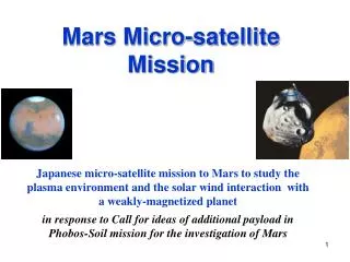
Study of Dust Detection System on a Micro Satellite Space Systems Dynamics Laboratory M2 Kyohei Nakashima
Contents • Objective • Background • Dust Detection System • Acoustic Emission Method • Experiments • Results • Conclusions
Objective • Analysis and verification of dust detection system on a micro satellite using Acoustic Emission sensors
Background • Space weather forecast is necessary because space disasters threaten human space activities. • Space disasters • Magnetic storm • High energy particlesradiation • Space debris Sun flares Space debris Magnetic storm Radiation Earth
Dust Detection System • Observation of surfaces of spacecrafts recovered • Example: LDEF (Long Duration Exposure Facility,), EURECA (European Retrievable Carrier ),SFU (Space Flyer Unit) G. Drolshagen, ESA/TOS-EMA21th IADC, 10-13 March 2003, Bangalore, India • High cost • Low Earth Orbit only
Acoustic Emission Method • Acoustic Emission (AE) is an elastic wave motion phenomenon in a solid. • AE occurs when an impact happens on a solid or when destruction happens in a solid. Impact destruction
Acoustic Emission Method • Impact position can be detected by solving the following equations. z S(x, y, z) TN(aN, bN, cN) T1(a1, b1, c1) y Ti(ai, bi, ci) T0(a0, b0, c0) S(x, y, z): Impact position Ti(ai, bi, ci): i th AE sensor position ve: Wave velocity ti: Arrival time of a wave at i th AE sensor x
Experiments • Two experiments were performed by • free fall. • a light gas gun. • Experiments by free fall are in preparation for impacts by a gas gun. • Experiments by a gas gun are representative of impacts in space.
Experiments • Free fall • 4 different types of panel and 1 type of projectile were used in free fall. • Projectiles were dropped from 380 mm above position of panels. • Impact velocity was about 2.7 m/s.
Experiments • Results of experiments by free fall Aluminum alloy panel CFRP layered panel
Experiments • Results of experiments by free fall Aluminum honeycomb sandwich panel Aluminum honeycomb sandwich panel with CFRP face sheets
Experiments • Gas gun • 4 different types of panel and 1 type of projectile were used in a gas gun. • Impact velocity was about 668.4 m/s. • Vacuum level was about 1.0*103 Pa
Experiments • Results of experiments by a gas gun Aluminum alloy panel CFRP layered panel
Experiments • Results of experiments by a gas gun Aluminum honeycomb sandwich panel Aluminum honeycomb sandwich panel with CFRP face sheets
Results • Aluminum alloy panel • compared real impact position with predicted impact position on experiments by free fall
Results • CFRP layered panel • compared real impact position with predicted impact position on experiments by free fall
Results • Aluminum honeycomb sandwich panel • compared real impact position with predicted impact position on experiments by free fall
Results • Aluminum honeycomb sandwich panel with CFRP face sheets • compared real impact position with predicted impact position on experiments by free fall
Results • Compared real impact position with predicted impact position on experiments by a gas gun Aluminum alloy panel CFRP layered panel
Results • Compared real impact position with predicted impact position on experiments by a gas gun Aluminum honeycomb sandwich panel Aluminum honeycomb sandwich panel with CFRP face sheets
Results • Aluminum alloy panel Error- 5.7 % of the distance of sensors • CFRP layered panel Error- 8.4 % of the distance of sensors • Aluminum honeycomb sandwich panel Error- 5.7 % of the distance of sensors • Aluminum honeycomb sandwich panel with CFRP face sheets Error- 7.6 % of the distance of sensors
Conclusions • Dust detection system is possible by using AE sensors. • It is more difficult to decide the arrival time accurately in panels using CFRP and honeycomb sandwich. • Buffers are needed to relieve the impacts to AE sensors. • There are little influence of holes by impacts to detect the impact points.