Download
1 / 7
70 likes | 118 Views
Implantation rates at the focal plane of Super-FRS Some Simulations for AIDA Detectors.

E N D
Implantation rates at the focal plane of Super-FRSSome Simulations for AIDA Detectors
Much intense primary beam much higher rates of parasitic fragmentspre-selection stage needed: pre- and main separator each equipped with a degrader very high energy up to 1.5GeV/uthe thickness of target and degraders have to be optimised to reduce losses due to secondary nuclear reactions
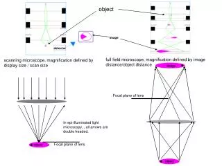
Simulation features • Optimum target thickness to maximise the production rate, a few g/cm2 • 1st degrader thickness and pre-separatotr slits to achieve feasible rate at F4 • 2nd degrader thickness and main-separator to achieve feasible rate at F6 (AIDA) • For better separation performance, both stages operated in achromatic mode, so the whole system is achromatic: the image size of the fragment at the final focal plane is independent of its momentum spread at the entrance of the system
Primary beam target fragment of interest total rate max. rate per strip • 58Ni(1 pnA) 9g/cm2 C 52Co 5000 5000 120 /strip • 124Xe(100 pnA) 7g/cm2 C 104Te 0.045 580 7 /strip • 124Xe(100 pnA) 7g/cm2 C 100Sn 0.3 1500 40 /strip • 124Xe(100 pnA) 6.5g/cm2 C 94Ag 3 2100 22 /strip • 144Sm(100 pnA) 4g/cm2 C 127Pm 6 2100 40 /strip • 206Pb(100 pnA) 5g/cm2 C 142Er 0.0025 200 5 /strip • 238U(100 pnA) 4g/cm2 Be 197Fr 2.3 35 0.4 /strip • 238U(1pnA) 78Ni 0.16 21k • 238U(1pnA) 140Te 40 55k 600 /strip • 238U(1pnA) 130Cd 0.15 300 25 /strip • 238U(1pnA) 129Ag 0.15 300 3 /strip • 238U(1pnA) 131Cd 0.15 1300 8 /strip • 150Nd(100pnA) 140Te 10 1200 40/strip • 150Nd(100pnA) 131Cd 1.2 100 1 /strip • 150Nd(100pnA) 130Ag 0.1 100 3 /strip
Implantation in the AIDA detectors After the last slit, we will be able to have wider beam profile in the AIDA detectors by defocusing with the quadrupoles behind. An energy degrader will be placed before the implantation detectors. The range distribution usually still is short enough for stopping one isotope in the same DSSD. Alternatively, the Super-FRS could be run in mono-energetic mode get a wider beam spread and a narrower implantation range in Si simutaneoulsly.
Simulation strategy in different phases • The design is changing, but main parameters have been fixed. • For fast estimation: LISE++ • For precise transmission : Mocadi • AIDA Performance: GEANT4