Download

1 / 38
390 likes | 408 Views
Pressure-driven Steady Pipe/Duct Flows. P M V Subbarao Professor Mechanical Engineering Department I I T Delhi. Natural Fluid Flows to Engineered Fluid Flows…. Popular Pressure Driven Creeping Flows. Fully developed duct/pipe Flow. Flow about immersed bodies.

E N D
Pressure-driven Steady Pipe/Duct Flows P M V Subbarao Professor Mechanical Engineering Department I I T Delhi Natural Fluid Flows to Engineered Fluid Flows…
Popular Pressure Driven Creeping Flows • Fully developed duct/pipe Flow. • Flow about immersed bodies. • Flow in narrow but variable passages. First formulated by Reynolds (1886) and known as lubrication theory, • Flow through porous media. This topic began with a famous treatise by Darcy (1856) • Civil engineers have long applied porous-media theory to groundwater movement. • http://www.ae.metu.edu.tr/~ae244/docs/FluidMechanics-by-JamesFay/2003/Textbook/Nodes/chap06/node17.html
Flow Regimes in Low Reynolds Number flows • Based on the Knudsen number magnitude, flow regimes can be classified as follows : • Continuum Regime : Kn < 0.001 • Slip Flow Regime : 0.001 < Kn < 0.1 • Transition Regime : 0.1 < Kn < 10 • Free Molecular Regime : Kn > 10 • In continuum regime no-slip conditions are valid. • In slip flow regime first order slip boundary conditions are applicable. • In transition regime (according to the literature present) higher order slip boundary conditions may be valid. • Transition regime with high Knudsen number and free molecular regime need molecular dynamics.
Major Contributions to Duct Flows • Jean Léonard Marie Poiseuille • Gotthilf Heinrich Ludwig Hagen • Gino Girolamo Fanno
J. L. M. Poiseuille • Poiseuille possess extraordinary sense of experimental precision. • He carried out his doctoral research on, ”The force of the aortic heart” in 1828. • Poiseuille invented the U-tube mercury manometer (called the hemodynamometer) and used it to measure pressures in the arteries of horses and dogs. • To this day blood pressures are reported in mm Hg due to Poiseuille's invention.
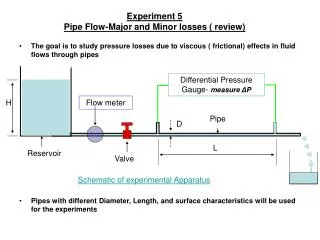
Study of Blood Flow in Capillaries Using Liquid flow in Glass Tubes • Poiseuille set out to find a functional relationship among four variables: • the volumetric efflux rate of distilled water from a tube Q, • the driving pressure differential P, • the tube length L, and • the tube diameter D. • Poiseuille summarized his findings at first stage by the equation Q = KP. • The coefficient K (named as Flow time) is a function of tube length, diameter, and temperature to be determined,
Law of Lengths • By investigating the influence of tube length Poiseuille was able to show that the flow time was proportional to tube length (the "law of lengths"). • At this point Poiseuille could state that K = K' /L. • Therefore, Q = K' P / L, where K' was a function of tube diameter and temperature.
Origin of Hydraulic Diameter • To assign a diameter to one of his noncircular, noncylindrical tubes, Poiseuille first calculated a geometrical average diameter for each end. • This was defined as the diameter of the circle having the same area as an ellipse with the maximum and minimum diameters of the tube section. • The arithmetic average of the geometrical means at the two ends was taken as the average diameter of the tube. • To determine the effect of tube diameter on flow, Poiseuille analyzed the data of seven of his previous experiments from which he was able to discern that the efflux volumes varied directly as the fourth power of the average diameter.
Poiseuille Law of Flow through Tubes • K" being simply a function of temperature and the type of liquid flowing. • For l0C, average value of K" = 2495.224 for distilled water expressed in mixed units of (mg/s)/(mm Hg) mm3•
Hagen’s Pipe Flow Experiments • Hagen was born in Köni gsberg, East Prussia, and studied there, having among his teachers the famous mathematician Bessel. • He became an engineer, teacher, and writer and published a handbook on hydraulic engineering in 1841. • He is best known for his study in 1839 of pipe-flow resistance, for water flow. • At heads of 0.7 to 40 cm, diameters of 2.5 to 6 mm, and lengths of 47 to 110 cm. • The measurements indicated that the pressure drop was proportional to Q at low heads.
Poiseuille Flow through Ducts • Whereas Couette flow is driven by moving walls, Poiseuille flows are generated by pressure gradients, with application primarily to ducts. • For incompressible flows:
Flow That follows Poiseuille’s Laws Regardless of duct shape, the entrance length can be correlated for laminar flow in the form
Fully Developed Duct Flow • For x > Le, the velocity becomes purely axial and varies only with the lateral coordinates. • v = w = 0 and u = u(y,z). • The flow is then called fully developed flow. For fully developed flow, the continuity and momentum equations for incompressible flow are simplified as: With
These indicate that the pressure p is a function of x only for this fully developed flow. Further, since u does not vary with x, it follows from the x-momentum equation that the gradient dp/dx must only be a (negative) constant. Then the basic equation of fully developed duct flow is subject only to the slip/no-slip condition everywhere on the duct surface This is the classic Poisson equation and is exactly equivalent to the torsional stress problem in elasticity
Characteristics of Poiseuille Flow • Like the Couette flow problems, the acceleration terms vanish here, taking the density with them. • These flows are true creeping flows in the sense that they are independent of density. • The Reynolds number is not even a required parameter • There is no characteristic velocity U and no axial length scale L either, since we are supposedly far from the entrance or exit. • The proper scaling of Poiseuille Equation should include , dp/dx, and some characteristic duct width h.
Dimensionless variables for Poiseuille Flow Dimensionless Poiseuille Equation
The Circular Pipe: Hagen-Poiseuille Flow • The circular pipe is perhaps our most celebrated viscous flow, first studied by Hagen (1839) and Poiseuille (1840). • The single variable is r* = r/R, where R, is the pipe radius. • The equation reduces to an ODE: The solution of above Equation is: • Engineering Conditions: • The velocity cannot be infinite at the centerline. • On engineering grounds, the logarithm term must be rejected and set C1 = 0.
The Wall Boundary Conditions: Regimes of Engineering Fluid Flows • Conventional engineering flows: Kn < 0.001 • Micro Fluidic Devices : Kn < 0.1 • Ultra Micro Fluidic Devices : Kn <1.0
Macro Engineering No-Slip Hagen-Poiseuille Flow The no-slip condition: For a flow through an immobile pipe: The macro engineering circular pipe-flow solution is thus
Dimensional Solution to Macro Engineering No-Slip Hagen-Poiseuille Flow
The Capacity of A Pipe • Thus the velocity distribution in fully developed laminar pipe flow is a paraboloid of revolution about the centerline. • This is called as the Poiseuille paraboloid. • The total volume rate of flow Q is of interest, as defined for any duct by
Mean & Maximum Flow Velocities • The maximum velocity occurs at the center, r=0. • The mean velocity is defined by
The Wall Shear Stress • The wall shear stress is given by
Friction Factor • w is proportional to mean velocity. • It is customary, to nondimensionalize wall shear with the pipe dynamic pressure. This is called as standard Fanning friction factor, or skin-friction coefficient. Two different friction factor definitions are in common use in the literature: Darcy Friction Factor
Micro Engineering Mild Slip Hagen-Poiseuille Flow The first order slip condition: For a flow through an immobile pipe:
The micro engineering pipe-flow solution is thus Mean & Maximum Flow Velocities The Wall Shear Stress Friction Factor
World's Longest Natural Gas Pipelines • West-East Pipeline : Length: 5,410 miles • Start: Xinjiang, China Finish: Shanghai • 2. GASUN Pipeline (planned) Length: 3,100 miles • Places: Starts in Bolivia, ends in Brazil • 3. Yamal-Europe Pipeline Length: 2,608 miles • World’s Longest Under Water Gas Pipeline, 1166km “Giant Serpent”
Indian Pipe Flow for Better economy & Ecology • Hajira-Bijapur-Jagdishpur (HBJ) Gas Pipeline: • This is 1,750 km long and connects Hazira in Maharashtra to Bijapur in M.P. and Jagdishpur in U.P. • This is the world s largest underground pipeline. tal city. • Jamnagar-Loni LPG Pipeline: • This 1,269 km long pipeline has been constructed by Gas Authority of India Limited (GAIL). • This is the longest LPG pipeline of the world. • It is like transporting 5.0 lakh cylinder per day. • It will result in net saving of Rs. 500 crore per year by eliminating road tanker movement and lead to reduction of about 10,000 tonnes of pollutant emission per year.
Frictional Flow in A Long Constant Area Duct The shear stress is defined as an average viscous stress which is always opposite to the direction of flow for the entire length dx. tw Divide by rAV2
Differential Equations for Frictional Flow Through Constant Area Duct
Differential Equations for Frictional Flow Through Constant Area Duct
Differential Equations for Frictional Flow Through Constant Area Duct
Compressible Flow Through Finite Length Duct Integrate over a length l
Maximum Length of A Pipe Using a Mean friction factor over a length l . The length of the duct required to give a Mach number of 1 with an initial Mach number Mi