Download
1 / 26
260 likes | 265 Views
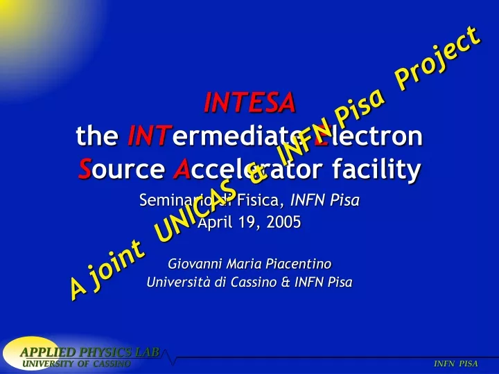
INTESA the INT ermediate E lectron S ource A ccelerator facility. A joint UNICAS & INFN Pisa Project. Seminario di Fisica, INFN Pisa April 19, 2005 Giovanni Maria Piacentino Università di Cassino & INFN Pisa. Presentation Overview. the Collaboration Motivations

E N D
INTESAthe INTermediate Electron Source Accelerator facility A joint UNICAS & INFN Pisa Project Seminario di Fisica, INFN Pisa April 19, 2005 Giovanni Maria Piacentino Università di Cassino & INFN Pisa
Presentation Overview • the Collaboration • Motivations • a short introduction on Microtrons and Microtron Injection; • INTESA: the INTermediate Electron Source Accelerator • Complex layout; • Magnetron Trigger & Modulation Circuit; • the RF Cavity: Design, Simulation and the prototype; • the INTESA beam injection; • other aspects; • Construction Status and Tests • Conclusions
the Collaboration • Università di Cassino • G.M. Piacentino, C.E. Pagliarone, B. Preite, J.F. Wyss • B., M. Boscia, van Basten, Alessandro • INFN di Pisa • A. Menzione,
Motivations • INFN Test Beam Source; • Radiation hardness studies on analogical and digital electronics; • X Ray Source; • Neutron Source; • Industrial Radiography Source; • Production of Radioisotopes; • Radiochemical and Radioactivation Analysis Lab;
in 1944 Veksler proposed a modification of cyclotron for electrons based on phase stability Veksler V.I., Dokl. Akad. Nawk USSR 43 (1944) 329 the electron trajectory in a Microtron is a system of circles increasing in diameter with a common tangent point where the accelerating cavity is placed. Microtron: Basic Principles
Microtron Injection Cathode inside the Cavity Toroidal Cavity Injection Kapitza I Electronic gun Injection Kapitza II
INTESA a General Overview In the original design we wanted to get: • Maximum Tunable Energy ~3 ÷ 20 MeV; • Range for the Current few nA up to 50-100 μA; • Possibility of Beam Extraction in Air; • High Beam Monocromaticity; • Small Emittance; • Small Accelerator size in order to reduce: • shilding and facility construction costs; • Maintance costs;
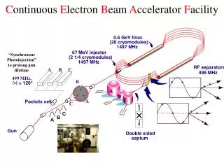
MAGNETRON TRIGGER AND MODULATION CIRCUIT MICROWAVE LINE MAGNETRON MICROTRON MAGNET AND EXTRACTION SYSTEM HIGH VOLTAGE POWER SUPPLY CONTROL DESK VACUUM PUMP Project Layout
INTESA the Microtron for INFN Pisa The main feature of INTESA are: • the Injection System: a Kapitza 2 based Injection procedure to maximize the injection and the Total beam Energy; • the Extraction System: • Tunable in Energy; • with a fixed extraction position; • Magnetron Power Supply: a Solid State one.
Machine Parameters • Fields • Injection Energy • Maximum Energy • Maximum orbit diameter • Maximum number of orbits
Magnetron Trigger & Modulation Circuit • RF Cavity will excited with an EM pulse RF=3 GHz, P=2.0 MW provided by a Magnetron (EEV, model M5015)
Magnetron Trigger & Modulation Circuit (cont’d) 6 LC Cells DT= 5 ms V= 8.5÷9.0 KV for 2 ms EEV, mod. M5015
Solid State Switch • Power SRC Mod. S03KX020KA assembled by Westcode on our specific design;
RF Cavity • The RF Cavity resonance frequency have been setted to be nRF= 3.0 GHz; • The RF Cavity sizes are: R=38.3 mm, h=15 mm; • The CavityQfactor is: • δ=1.22*10-4 mm is the penetration depth in the copper for at a frequency of 3 GHz. • Shunt Resistence: • For a 580 KeV impulse we get:
RF Cavity simulation performed with FEMALBMATHLAB
RF Cavity simulation (cont’d) performed with FEMALB MATHLAB
Prototyping the RF Cavity • Oxygen free high density Copper manufactured in Cassino.
Possibility of changing the beam current remaning into the VSWR Magnetron limits; Wave Guide - RF Cavity Coupling
beam injection: Kapitza II • Choosen a Kapitza II Injection system for INTESA; • the cathode is inside the RF cavity; • beam tuning up to ~20%; • DE= 580 keV;
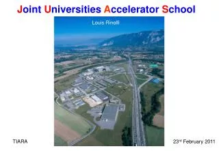
Microtron Magnet & vacum Chamber in San Piero a Grado (PI)
Construction Status & Tests Many Parts to be realized • Microwave System; • Coupling of Resonator with a Waveguide; • Automatic Frequency Control System; • Microwave Power Supply; • Extraction of Electron Beam; • Vacuum System; • Magnetic Field and Cooling System; in particular…
ATTIVITA’DETTAGLIO TEMPI COSTI DONE-INPG TODO
ATTIVITA’DETTAGLIO TEMPI COSTI DONE-INPG-TODO
Conclusions • the Project is pretty much at an advanced state; • All the electronic components are ready and tested; • RF cavity … • xyz needed in order to achieve the goal of building the facility for the end of xx year


![Int [] a = new int [4];](https://cdn1.slideserve.com/2729093/slide1-dt.jpg)