Download
1 / 38
380 likes | 451 Views
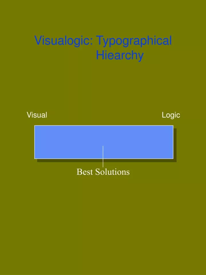
Visualogic: Typographical Hiearchy. Visual Logic. Best Solutions. Visualogic: Typographical Hiearchy . Visual. Logic. Best Solutions. Visual logic lies equal distance between the visual elements

E N D
Visualogic: Typographical Hiearchy Visual Logic Best Solutions
Visualogic: Typographical Hiearchy Visual Logic Best Solutions Visual logic lies equal distance between the visual elements and the logical elements. Visualogic is a term that describes how a person best uses the visual and logical aspects of typography to make a text both accessible and beautiful to the reader. The best solutions to the conflict involving the eye and the intellect lie somewhwere between the two, in the middle of the spectrum.
Visualogic: Typographical Hierarchy Visual Logic Best Solutions • Reveal the Hierarchy! • Identify and typographically express the • hierarchy in the messages. • Evaluate the Solutions as to Their Hierarchy. • Evaluate ideas in front of your eyes. • Don’t just think about ideas.
Hierarchy • Mortal Sin Hierarchy is not revealed. A wrong association remains. • Venial Sin Hierarchy is almost crystal clear. Some opportunities have been missed. • Judgment Call Hierarchy is crystal clear. Document is good, but perhaps not the greatest. --Bruce Ian Meader, Rochester Institute of Technology
Objectives • To discover the power of typographi-cal signs for clarity and immediacy. • To discover how typographical signs affect the message to the reader. • To discover how typographical signals serve as visual cues to signal the hierarchical levels and associations in a text. • To acquire a methodology for approaching all messages. --Bruce Ian Meader, Rochester Institute of Technology
Legibility Criteria for Choosing Typefaces • Character Level • Word Level Context/ Document Level Bottom Up Top Down
Legibility Typeset Documents Typewritten Documents Hyphen - - Hyphen En dash _ - Hyphen Em dash — -- Double Hyphens You must now use the symbols for typeset documents. Sometimes an em dash simply is too long, so use an en dash. Hyphens are used to hyphenate words.
Legibility Definition of Legibility: How well a typeface supports the processes of fluent reading. • The easiest checks on legibility are those at the character level. • Checks on characters in context give a better feel how a typeface will work when it is being read. • Legibility checks must be done on paper since screen resolution is too course. • Give your readers a choice between two typefaces, and ask them for their preference in terms of readability.
Legibility: Character Level • Check typefaces for any quirky characters that may catch the the reader’s attention, giving unintended emphasis to certain words using that character. • Check for characters that are likely to be confused with one another, bearing in mind the context of the character. 1. The numeral ‘1,’ the capital letter ‘I,” and the letter ‘l’ are often confused. 2. Some reversed letters at lower resolutions are often confused. 3. Some italic letters are often confused.
Legibility: Character Level Sans Serif Type: Without Tails Bagging Baseline Ascender Height x-height Descender Height no tail • The x-height itself may not be the sole contributor to legibility. Typefaces with large x-heights often have wider characters and may also require more vertical space than typefaces with small x-heights. • Typefaces with large x-heights appear larger and, thus, reproduce well in printing and photocopying.
Legibility: Character Level Serif Type: With Tails BaggingBaseline Ascender Height x-height Descender Height tail • The x-height itself may not be the sole contributor to legibility. Typefaces with large x-heights often have wider characters and may also require more vertical space than typefaces with small x-heights. • Typefaces with large x-heights appear larger and, thus, reproduce better in printing and photocopying.
Legibility: Word Level Vertical Dimension BaggingBaseline Ascender Height x-height Descender Height tail • Check that there is enough difference between x-height and ascender height for overall word contour. Too, clarity of word contour will • depend upon the vertical spacing provided.
Legibility: Word Level Horizontal Cohesion • Check the lateral spacing of a sample text. Characters should not be colliding with each other or be so far apart that they appear to be two separate words. • Reversed type often appears cramped without lateral adjustment. • Small capitals appear cramped without lateral adjustment. • Some bold typefaces have disproportionately large word spaces. • Justified text has less consistent character and word spacing than does ragged text.
Legibility: Word Level Horizontal Cohesion • Warning: If you are using tracking or letter-spacing to make global adjustments, global alterations often improve some character combinations but not all. • Kerning can be used in your program to improve letter combi binations that are too loose or too tight. Kerning is especially useful in titles and headers, where the type size is larger. You must remember that certain character combinations are naturally widely spaced, e.g. ‘vy’ and ‘ry.’ Kerning will only make them touch.
Legibility: Context/Document Level To differentiate and emphasize elements of a document and yet have unity sounds contradictory. But typeface families are designed to do that. • Documents usually comprise different elements, such as footnotes, formulae, captions, index, headings, and so. • Some of these elements need to be differentiated typographically, not just by their content or position on the page. • Some of these element sneed to be emphasized typographically in relation to other elements. • Simulanteously, different elements of a text should form a visual unity.
Legibility: Context/Document Level One or Two Typeface Families? • If one typeface can adequately distinguish all the necessary elements of a document, then use only one typeface. Different text elements set in regular, italic, bold, condensed, or other variants of one typeface should be quite distinguishable but related in style.
Legibility: Context/Document Level One or Two Typeface Families? • Sometimes one typeface family cannot represent all the necessary elements. Then you will need to com-bine two, but rarely more than two, typeface families in one document.
Legibility: Context/Document Level Two Typeface Families in a Document • The effectiveness with which two typeface families work together depends partially upon the features of the characters, i.e. they must be quite dissimilar in appearance: • Serif or sans serif • Degrees of contrast in heights and widths SerifSan Serif pagepage contrast in thicknesses no contrast in thicknesses light weight light weight not wide wide not so high higher
Legibility: Context/Document Level Differentiation with Emphasis • Necessary in the heading structure of a text or to draw attention to particular text elements • First consider variant of main text face • Necessary high resolution for printer (c. 640 dpi) • There should always be more vertical space above a heading than below a heading.
Legibility: Context/Document Level Differentiation Without Emphasis • Combine typefaces that contrast in style, not size, width, or weight. • Combine typefaces of different scripts • Combine text typefaces with symbols, but be careful of the vertical height
Legibility: Context/Document L Level Main Variables of Documents Affecting Individual Typefaces: • Vertical spacing • Type size • Word spacing • Line length
Legibility: Context/Document Level Coordingating Typeface and Document Format • Vertical spacing should be adequate for text content and typeface. • Horizontal spacing, justification mode, and line length should be adjusted to give evenly spaced text. • Look at the relation of the text area to the page as a whole.
Legibility: Context/Document Level Spatial Relationships Between Text and Page • Do not attempt to set any typeface to the format of a typewritten page. The pages of text will appear dense and unappealing. • Do not use the default setting for line length for line length. • Text at large page sizes should be surrounded with a lot of space or set in columns. • Text in a single column on a page should have wide characters.
Legibility: Context/Document Level Matching Typefaces to Document Genre (Top Down) • Consider the conventions of the document to be produced. • Avoid too much formality. • Conventions should be appropriate to the typeset, printed document, not to a typewritten document.
Legibility: Context/Document Level Appropriateness • Use Orator • For highly legible lecture notes • For simple legible type • For tabular charts where character alignment is needed • Test the typeface in your document. • Use New Century Schoolbook • For lengthy text applications. • For adverse printing conditions. • When maximum legibility is necessary.
Legibility: Context/Document Level Formality vs. Informality High contrasts Soft Contours Fine details Vertical or regular letterforms • Reduce level of formality • with an asymmetrical page format. • by ragging, rather than justifying, the text. • by not using capitals in headings.
CHARLEVOIX, MICHIGAN WATER SUPPLY SYSTEM IMPROVEMENTS INTRODUCTION The purpose of this investigation was to review the adequacy of the present Charlevoix water supply system to meet present and anticipated future water demands of the community. The present system was installed in 1922, when the permanent population of Charlevoix was about 2200. The population since then has doubled, and recent projections indicate that the population will double again by the year 2000. The following questions therefore arise: 1. Does the present system have a maximum safe capacity to meet projected water demands? 2. Are the pumping, distribution, and elevated storage facilities capable of meeting projected demands? 3. Are these facilities capable of meeting recommended fire flow for the projected population? The present system also lacks the disinfection facilities now required by the State for all municipal water supplies. To evaluate the adequacy of the present water supply system in the face of future demands, the study uses population projections to establish future requirements and analyzes the capacity, equipment, and facilities of the present system. A comparison of future requirements with the abilities of the present system. A comparison of future requirements yields the recommendations for improvements of the Charlevoix water supply system. We use existing records, field studies, and earlier engineering reports to determine the needs of the water system. We review all general areas of the present system plus some additional construction to bring the total system up to levels sufficient to meet anticipated requirements. The report presents the
estimaed total cost of the projects and a breakdown of costs for reach part of the project. The report is divided into the following main sections: I. WATER SUPPLY REQUIREMENTS. This section analyzes the trends of population growth, pumping patterns, and per capita consumption in order to project future design flow requirements. II. THE PRESENT WATER SYSTEM AND RECOMMENDED IMPROVEMENTS. This section compares the future requirements with improvements. III. COST ESTIMATES. This section itemizes the estimated costs for the improvement recommended.
CHARLEVOIX, MICHIGAN WATER SUPPLY SYSTEM IMPROVEMENTS INTRODUCTION The purpose of this investigation was to review the adequacy of the present Charlevoix water supply system to meet present and anticipated future water demands of the community. The present system was installed in 1922, when the permanent population of Charlevoix was about 2200. The population since then has doubled, and recent projections indicate that the population will double again by the year 2000. The following questions therefore arise: 1. Does the present system have a maximum safe capacity to meet projected water demands? 2. Are the pumping, distribution, and elevated storage facilities capable of meeting projected demands? 3. Are these facilities capable of meeting recommended fire flow for the projected population? The present system also lacks the disinfection facilities now required by the State for all municipal water supplies. To evaluate the adequacy of the present water supply system in the face of future demands, the study uses population projections to establish future requirements and analyzes the capacity, equipment, and facilities of the present system. A comparison of future requirements with the abilities of the present system. A comparison of future requirements yields the recommendations for improvements of the Charlevoix water supply system. We use existing records, field studies, and earlier engineering reports to determine the needs of the water system. We review all general areas of the present system plus some additional construction to bring the total system up to levels sufficient to meet anticipated requirements. The report presents the
estimated total cost of the projects and a breakdown of costs for reach part of the project. The report is divided into the following main sections: I. WATER SUPPLY REQUIREMENTS. This section analyzes the trends of population growth, pumping patterns, and per capita consumption in order to project future design flow requirements. II. THE PRESENT WATER SYSTEM AND RECOMMENDED IMPROVEMENTS. This section compares the future requirements with improvements. III. COST ESTIMATES. This section itemizes the estimated costs for the improvement recommended.
Atlantic Shipbuilding MEMORANDUM File No. 12-5T Date 3 July 1986 To: S. Guthrie Assistant General Manager From: J. Andrulis, Manager Producing Engineering Subject: Proposal to Introduce Line Heating Technology into ASBC Production Procedures At present time, the technique of cold-forming shell plating limits our productivity and flexibility. The fact that we rely on this technique limits our competitiveness in some bid situations. I therefore propose that ASBC introduce line heating technology in our facilities, and have scheduled a meeting on 16 July 1986 to discuss this proposal and its implementation. I believe this is an important matter, as line heatingtechnology will enable us to stay competitive with other U.S. shipyards. Line heating technology will (1) increase our productivity, (2) facilitate more complex shell plate curvature and lower costs, and (3) improve production flow. Improved fabrication quality will result in the yard being more competitive. Implementation of line heating technology will require approximately one year, including planning. Limitations of cold forming technique. Our facilities for cold-forming shell plating do not suit the the needs of current designs. These facilities can perform adequate shaping only up to 3/4 inch thick plate and are not capable of giving plates longitudingal curvature. The specifications of our cold-forming facilities and optimal specifications for contract TY 236-83 are listed in Appendix A. Line heating technology. Line heating is the process of inducing curvature in structural shapes and plates by controlled heating and cooling. The process is also scientifically applied for fairing structural intersections and removing distortion due to thermally induced stress. Advantages of line heating for forming curved shell plating. By utilizing line heating technology, we can eliminate the restrictions we now face in the forming of shell plating. The advantagaes of line heating are: .
1) Increase in productivity, as seen in other U.S. shipyards (Appendix B). 2) Ability to accurately form shell plates with compound curvature (Appendix C itemizes parameters and dimensional control for plates on Hitachi Hull Y-14-2), which results in a cost savings. 3) Ability to accurately fit curved parts to curved shell with minimal force, which requires fewer man-hours than cold forcing. 4) Accommodation of larger plate sizes, thereby minimizing butts and seams. 5) Optimization of existing facilities through improved scheduling and elimination of bottlenecks. 6) Facilitation of subsequent assembly by eliminating distortion prior to forwarding an interim product to the next level of production. 7) Ability to accurately and productively fair structural intersections. 8) Enhanced worker safety. Our statistical accuracy control system would be modified to assure the normal process capability, including standard range and tolerance limits. In conclusion, line heating shapes material more accurately with less effort and provides more production flexibility. Implementation of line heating. Introduction of line heating would be best accomplished by contracting with a Japanese firm to provide technical information and training. Our own shipyard would be responsible for the adaptation of existing equipment and the construction (and purchase) of new equipment needed for this method. Finally, ABS approval will be needed before this technique is adopted in actual production. The implementation of line heating will require approximately one year. Upon approval of this proposal I will prepare a detailed procedure and cost estimate for implementation of line heating technology. Final cost estimates can be made after technical training with the Japanese firm. Qualitative benefits then can be calculated for selected proposals and contracts, based on the percentage of shell plates which could be formed in whole or part by line heating.
I have schedule a meeting in the Administrative Conference Room for 0900 16 July 1986 to discuss this proposal and implementation plans. Appendices: A-Yard Specifiation and optimal specification, Contract TY236-43 B-Effect on Productivity of Line Heating Technology C-Compuond Shell Curvature of Hitachi Hull Y-14-2 cc: S. Gutherie, Asst. General Manager V. White, Quality Assurance G. Landon, Prod. Engineering F. Domino, Construction C. Sherman, Welding Engineering W. Loman, Purchasing A. Vaslo, Chief Naval Architect
Atlantic Shipbuilding MEMORANDUM File No. 12-5T Date 3 July 1986 To: S. Guthrie Assistant General Manager From: J. Andrulis, Manager Producing Engineering Subject: Proposal to Introduce Line Heating Technology into ASBC Production Procedures At present time, the technique of cold-forming shell plating limits our productivity and flexibility. The fact that we rely on this technique limits our competitiveness in some bid situations. I therefore propose that ASBC introduce line heating technology in our facilities, and have scheduled a meeting on 16 July 1986 to discuss this proposal and its implementation. I believe this is an important matter, as line heatingtechnology will enable us to stay competitive with other U.S. shipyards. Line heating technology will (1) increase our productivity, (2) facilitate more complex shell plate curvature and lower costs, and (3) improve production flow. Improved fabrication quality will result in the yard being more competitive. Implementation of line heating technology will require approximately one year, including planning. Limitations of cold forming technique. Our facilities for cold-forming shell plating do not suit the the needs of current designs. These facilities can perform adequate shaping only up to 3/4 inch thick plate and are not capable of giving plates longitudingal curvature. The specifications of our cold-forming facilities and optimal specifications for contract TY 236-83 are listed in Appendix A. Line heating technology. Line heating is the process of inducing curvature in structural shapes and plates by controlled heating and cooling. The process is also scientifically applied for fairing structural intersections and removing distortion due to thermally induced stress. Advantages of line heating for forming curved shell plating. By utilizing line heating technology, we can eliminate the restrictions we now face in the forming of shell plating. The advantagaes of line heating are: .
1) Increase in productivity, as seen in other U.S. shipyards (Appendix B). 2) Ability to accurately form shell plates with compound curvature (Appendix C itemizes parameters and dimensional control for plates on Hitachi Hull Y-14-2), which results in a cost savings. 3) Ability to accurately fit curved parts to curved shell with minimal force, which requires fewer man-hours than cold forcing. 4) Accommodation of larger plate sizes, thereby minimizing butts and seams. 5) Optimization of existing facilities through improved scheduling and elimination of bottlenecks. 6) Facilitation of subsequent assembly by eliminating distortion prior to forwarding an interim product to the next level of production. 7) Ability to accurately and productively fair structural intersections. 8) Enhanced worker safety. Our statistical accuracy control system would be modified to assure the normal process capability, including standard range and tolerance limits. In conclusion, line heating shapes material more accurately with less effort and provides more production flexibility. Implementation of line heating. Introduction of line heating would be best accomplished by contracting with a Japanese firm to provide technical information and training. Our own shipyard would be responsible for the adaptation of existing equipment and the construction (and purchase) of new equipment needed for this method. Finally, ABS approval will be needed before this technique is adopted in actual production. The implementation of line heating will require approximately one year. Upon approval of this proposal I will prepare a detailed procedure and cost estimate for implementation of line heating technology. Final cost estimates can be made after technical training with the Japanese firm. Qualitative benefits then can be calculated for selected proposals and contracts, based on the percentage of shell plates which could be formed in whole or part by line heating.
I have schedule a meeting in the Administrative Conference Room for 0900 16 July 1986 to discuss this proposal and implementation plans. c Appendices: A-Yard Specifiation and optimal specification, Contract TY236-43 B-Effect on Productivity of Line Heating Technology C-Compuond Shell Curvature of Hitachi Hull Y-14-2 cc: S. Gutherie, Asst. General Manager V. White, Quality Assurance G. Landon, Prod. Engineering F. Domino, Construction C. Sherman, Welding Engineering W. Loman, Purchasing A. Vaslo, Chief Naval Architect
Legibility: Context/Document Level Vertical Spacing andType Size • Do not accept the default (‘auto’) vertical space settings. Word spacing, justification mode, and line length: • Ideally, word spaces should be about the width of the narrowest character of a font, i.e. the width of the lower case ‘i’ in serifs and slightly less in sans serif. • Software packages tend not to allow much control over the word spacing of justified text. This makes hyphenation necessary. • Local changes in text spacing can greatly alter the ‘color’ or appearnace of a typeface in text.
Visualism • Typography is the visual representation of language. Identify and express the correlation between language (the spoken word) and typography (the mass-produced word). • Make it beautiful! Emphasize the internal correlations: the typographic shapes, proportions and shapes of white spaces, and variations in all the components. • Use inflection and emphasis in messages we hear and see. • Make the message accessible, clear, and interesting.