Download
1 / 30
300 likes | 509 Views
The Spectral Method: Its Impact on NWP Ferdinand Baer Department of Meteorology University of Maryland College Park, MD 20742. Symposium on the 50th Anniversary of Operational Numerical Weather Prediction 14–17 June 2004, The Inn and Conference Center, College Park, MD 20742.

E N D
The Spectral Method: Its Impact on NWPFerdinand BaerDepartment of MeteorologyUniversity of MarylandCollege Park, MD 20742 Symposium on the 50th Anniversary of Operational Numerical Weather Prediction 14–17 June 2004, The Inn and Conference Center, College Park, MD 20742
General features of a NWP model Let a vector B represent N dependent variables describing the state of the prediction system at any time, B = {Bb} = (V s qv qi ql aj )T The prediction system is, or, F has the dimensions of B, and depends nonlinearly and differentially on B, r and t. A linear matrix operator L is often used to transform these equations. Convert this system to computational form for prediction. We will focus on finite-difference and spectral methods, since they are most popular. (1) (2)
The finite difference process Select a three-dimensional grid with M points to approximate the space continuum; Select a difference operator for derivatives; Represent B at each point as a vector of dimension NM; F becomes a numerical vector with NM elements after applying the difference operator at each grid point; L, by virtue of the difference operator, is an (NM x NM) matrix. Using a circumflex to represent numerical vectors and matrices at gridpoints, the finite difference system is, (3)
Select a truncated set of linearly independent, continuous global structures, Za and expand the model variables Bb in them, Since L = {Lb} is diagonal, the scalar form of (2) is, Substitution of (4) into (5) leads to an error equation, which can be solved for the unknown Bb,a by multiplying it by test functions and requiring the integral over the domain to vanish, yielding NMe spectral equations for , To detemine Fb, let Bb (Bb,a) and Z (Za) with Me elements; The spectral method (4) (5) (6)
The spectral method (cont.) And (6) yields Me prediction equations for the expansion coefficients, Define matrices , and . If Bs (Bb) and Fs (Fb) are extended vectors for the expansion coefficients including all variables, The grid point values from this spectral representation are calculated at each point (ix1, jx2, kx3) for each dependent variable Bb by use of (4) and can be compared to the FD eq.(3); Note the structural similarity of these equations! (7) (8) (9) (3)
Specifics of the spectral method used for NWP Use on horizontal surfaces: Let the expansion functions Za satisfy the eigenvalue problem, Lb Za= -cb,a Za Orthogonality and normality, Test fctns. = Exp. fctns., Use solid harmonics, With Za = Y , = (n + im), Lb2 and The expansion (Eq.4) becomes (11) expansion coefficients
Spectral Barotropic Vorticity Equation • Convert to vorticity and divergence; • And the BVE in term of becomes, • In spectral form, the BVE is, (12) (13)
Computational features of the spectral method Interaction coefficient method Use BVE for demonstration: From (11), (12) and (13) the nonlinear term is F ; Interaction Coefficients (IC) I,, Time change of any depends on the coupling of all allowed . The IC set depends on model truncation. Its size is ~n5, the largest allowed index. It can be computed once and stored. The general system (2) can be represented identically but has more variables. However, some variables may not expand effectively and create computing problems.
Computational features of the spectral method Transform method An alternate method for calculating F; also use BVE for demonstration: Integrand in (13)--nonlinear terms-- is transformed onto a special grid and solved exactly by quadrature; Derivatives in F() are taken before evaluation on the grid; Number of calculations is of order n3 (n is the max number of grid points) hence a dramatic saving in computing time; Since forcing functions are summed over the grid, those functions with near local singularities are smoothed out; The general system (2)can be represented identically but with more variables. This procedure made the spectral method a popular alternative to FD methods.
Advantageous features of the spectral method Linear instability and phase errors The general prediction equation (9) can be written with a linear and nonlinear terms; Diagonalize C and solve the linear part of the equation; Transform Bs with this solution, thereby removing it from equation (15); Then the resulting system cannot have linear instability or linear phase errors; This is more cumbersome with the FD method which can yield systematic linear phase errors and possibly linear instability. (15)
Advantageous features of the spectral method Nonlinear instability First discussed by Phillips (1959); Eq. (3) includes nonlinear terms of the form u∂u/∂x for calculating ∂u/∂t ; Let A component of the nonlinear product for two waves mi, mjis, When mi+ mjM, the FD form for ∂u/∂t cannot see this term and it is folded back into the range mi+ mj< M causing an aliasing error and ultimately leading to instability. To prevent this instability, scale dependent artificial friction is introduced to prevent the error from growing. This error is completely avoided in the spectral method since terms which exceed the allowed range of the expansion functions need not be calculated.
Advantageous features of the spectral method Conservation Conservation conditions inherent in the differential equations should be maintained in the computational system; The BVE, as an example, demonstrates that the abs. vorticity or any function thereof must be conserved following a particle or on integration over all particles. This is difficult to achieve with the FD method; however Arakawa (1966) satisfied conservation of vorticity, enstrophy and energy over the global surface by manipulation of the Jacobian operator (nonlinear advection), although the method may not be unique; Platzman (1960) and Lorenz(1960) independently demonstrated that the spectral BVE, when truncated, satisfies all appropriate conservation conditions without application of additional techniques; Experiments with the spectral shallow water equations, which involve cubic nonlinearity, show small errors in conservation.
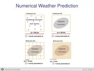
Advantageous features of the spectral method The polar problem Finite difference methods: Mapping to a grid is complex in polar regions; The simple procedure of using a lat.-lon. grid requires no mapping and has become popular; Approaching the poles the length of the increment decreases as cos(), thus requiring a shorter t to satisfy the CFL criterion; Numerous ‘fixes’ have been tried such as reducing the number of elements as one approaches the pole; This requires arbitrary scale truncation which may distort the solution because of nonlinearity. Spectral method: In the spectral system, scales are directly represented by expansion in wave number, thus no special truncation is needed; All selected expansion functions are regular at the pole, hence no convergence problems exist there.
Scaling in the vertical Use a simplified equation like the Quasi-Geos. Pot. Vort. Eq. (QGPVE) which has linear solutions, The vertical structures can be constructed from the vertical part of the L operator having eigenvalues which are the vertical scaling numbers, equivalent depths, (For simple thermodynamic profiles and BCs, these structures are Bessel functions in the vertical.) Spectral applications for insights Horizontalvertical equivalent depth 3-D index
Truncation This is essential to close a model. With the finite difference method, one has many alternatives in grid dimensions, distribution, etc. 2-D truncation with the spectral method At a specified wave number = (n + im)max; At a specified ordinal index, nmax, and mnmax: denoted astriangular truncation; At mmax and n n + mmax; denoted as rhomboidal truncation. (b) and (c) have been most popular: energy in atmospheric surfaces converges rapidly with both truncations; Relative advantages: For (c) each planetary wave has equal resolution; For (b) it is simpler, more computationally economical, and depends on a single scale index (n). Additionally, some observational data tends to distribute along lines of constant n.
Average KE (both ht. and time) as percent of total in each wave component = n +im. U-ENERGY V-ENERGY Zeros in latitude (n - m) Zeros in latitude (n - m) Planetary wave m Planetary wave m
3D truncation with spectral model 0 10 20 30 40 50 60 70 80 Horizontal index - n 2 4 6 8 10 12 14 16 18 Vertical index - k Can truncate the model for fixed values of s based on the QGPV Eq.,
3D truncation with spectral model-- Where to put the levels? • One can find levels in the atmosphere on which numerical structures of the QGPV eq. converge to the exact solutions. These can be used as optimum vertical levels in a FD vertical and spectral horizontal representation. See example below. Optimized -levels in mb. No. of levels
Brief history of spectral modeling First attempted in early 1950s; First became popular in the 1960s; First successful PE model by Bourke (1974); Implemented by Canadians and Australians in 1976; Adopted by NMC in 1980; By the French in 1982; By ECMWF in 1983; In 1998, ECMWF was running at T213; In 1999 NCEP was running at T254. ???????????????
Summary Breakthrough for spectral models came with the transform method since it became computationally competitive with the FD method. The spectral method has some advantageous features: It can eliminate linear instability and phase errors; It prevents a form of nonlinear instability automatically; It avoids the pole problem; It has clear scaling scaling properties; It can be systematically truncated based on scaling; It can give insight into 3D truncation based on horizontal and vertical coupling. Since new computational methods are still being developed, the future for NWP modeling is still up in the air.
Have A Happy 50th
Spectral applications for insights Scaling A prelude to truncation. In physical space, scales are determined by grid elements x. In the spectral domain, scales are determined by wave numbers; i.e., transforms from the gridded lengths. Scaling in the 2-D spectral domain Consider the Laplace operator from scale analysis, where l is an index representing the # of sub-regions in s2, the area of the domain.
Cartesian domain: Assume a function such that, This 2-D index depends on both dimensions and their indices. Spherical surface: Assume a function such that, Here the 2-D index depends only on a single scale index n ,and linearly for 1. Spectral applications for insights 2-D Scaling (cont.)
Cellular structure of solid harmonic functions Yn,m for n=5 and all allowed values of m.
Use QGPV model. Operator L has eigenvalues which depend on the horizontal index n and equiv. depth hk, These indices can be used for 3D scaling. 3-D Scaling 3D truncation limits on modes k and n as determined by the limit on s.
Original style; consider only computation cycle speed and memory. Innovations since; vector calculations multiprocessors. Current primary issue; models need more power than is available, thus one must make use of machines most efficiently. The computational world
Define a "computing cycle" to be that time required to do once all calculations which are systematically repeated to complete the entire calculation. For conventional marching problems this computing cycle is one complete time step. On a serial machine the computing cycle is the total time for that operation and can only be reduced by a faster machine. On a MPP the computing cycle is reduced insofar as many computations can be performed simultaneously. The time required to complete this cycle should converge to the time needed by the machine to perform one computation (the machine cycle) as the number of processors is increased. The computational world (cont.)
Consider a SIMD parallel processor; Distribute I,one to a processor; Send pairs to appropriate processors; Calculate all contributions in one cycle; Sweep, sum and repeat. In limit, this process can approach one machine cycle. We calculated the BVE at LANL on a CM-5 using this scheme and compared to the transform method with comparable speed. Additionally, a baroclinic model showed similar results. Unfortunately, SIMDs have disappeared. Example of using this process with the interaction coefficient method.