Download
1 / 112
1.12k likes | 1.12k Views
Learn about the clean room requirements and radon abatement strategies for the CUORE experiment, including layout designs, PSA storage options, and timing constraints.

E N D
CUORE Clean Room Robin Lafever LBNL LNGS Robin Lafever LBNL, LNGS
Overview Overview Timing Radon-free strategies Radon-Box Concept All N2 assembly Local Radon Abatement Clean Room Layouts PSA studies Extended Clean Rooms Specifications Soft Enclosures Hard enclosures Testing Full scale mockups Proof-of-concept Models Material screening Robin Lafever LBNL, LNGS
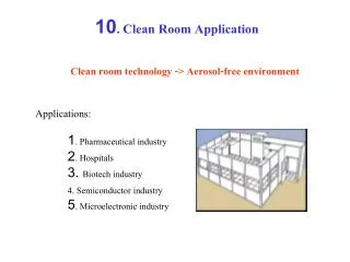
Overview In April 2008, studies were started to define the Clean Room requirements and develop Radon abatement strategies. In addition to reviewing requirements imposed by assembly and operation scenarios, PSA storage in the Clean Room area was also studied. Clean Room design and Radon abatement were eventually approached as separate problems each with unique requirements. A general Clean Room specification was developed, and Radon abatement was expanded into three competing strategies Robin Lafever LBNL, LNGS
Crystal Assembly Layout Starting point is the layout from SilvioMorganti’s assembly scenario shown in the ‘zeropuntquindici’ document. Crystal and Tower assembly is done under N2 glove boxes. During this time, the Cryostat is being assembled and tested, and the Cryostat room is open to outside air at several times for loading assemblies and major components Robin Lafever LBNL, LNGS
Tower Integration Layout Detector assembly is also done under N2 glove box, then moved into the Cryostat room for mounting to the Cryostat. Early plans were to do this in open air with exposure limited by time. Robin Lafever LBNL, LNGS
PSA Layout studies-3 In mid April 2008, a series of studies was conducted to attempt to accommodate the desire to place the place the Permanent Storage Area (PSA) in or near the CUORE clean room assembly area. The intent was to evaluate the feasibility of placing the PSA in a clean room/Radon-free environment, if possible. With discussion, an additional requirement evolved to keep the PSA and assembly areas separate to avoid traffic and possible interference between Storage and Assembly operations. , Robin Lafever LBNL
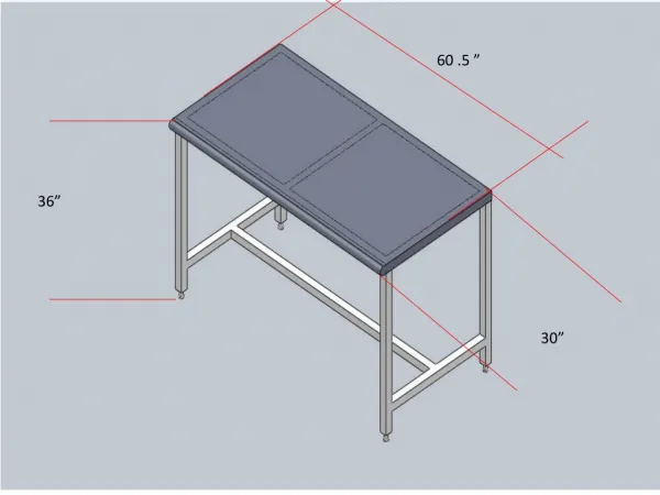
Typical PSA cabinet used in these layouts is based on a Type A, Series 400 Stainless Steel unit from Terra Universal. Robin Lafever LBNL
Default Clean Room layout.This configuration conforms closely to that shown in the Morganti document zeropuntoquindici Robin Lafever LBNL
Default Clean Room layout Iso view shows placement of the doors and placement of some of the assembly hardware Robin Lafever LBNL
Default Clean Room layout drawing with basic room dimension and floor area Units are in Meters Robin Lafever LBNL
Extended Clean Room layout with PSA cabinets .The cabinet arrangement is arbitrary and is only one of many studied. This layout includes a separate Gowning chamber and is consistent with the desire to keep PSA storage out of traffic areas during assembly operations. Robin Lafever LBNL
Extended Clean Room layout Iso view showing the doors and another PSA cabinet arrangement.Note the repositioning of the large equipment access door directly into the Cryostat area. Robin Lafever LBNL
Extended Clean Room layout drawing with basic room dimension and floor area Units are in Meters Robin Lafever LBNL
Cat walk study and extended Clean Rooms Alternative PSA storage was considered in the Cuoricino clean room level and included the desire to transport crystals and sub assemblies safely from the Cuoricino deck to the Cuore deck with out the risk of using several stairs and level changes Early June, requirements for PSA storage in the Clean Room were ruled out, however an expanded Clean Room was approved as additional assembly space. Robin Lafever LBNL, LNGS
Catwalk Robin Lafever
Catwalk Robin Lafever
Catwalk Robin Lafever
Clean Room Layouts Robin Lafever LBNL, LNGS
Cuore Hut with stair access Robin Lafever LBNL, LNGS
Default Clean Room layout showing Cryostat utility conduit Robin Lafever LBNL, LNGS
Default Clean Room layout showing Cryostat utility conduit Robin Lafever LBNL, LNGS
Extended Clean Room version A Robin Lafever LBNL, LNGS
Extended Clean Room version A Robin Lafever LBNL, LNGS
Extended Clean Room version B Robin Lafever LBNL, LNGS
Extended Clean Room version B Robin Lafever LBNL, LNGS
Extended Clean Room version C Robin Lafever LBNL, LNGS
Extended Clean Room version C Robin Lafever LBNL, LNGS
Timing Robin Lafever LBNL, LNGS
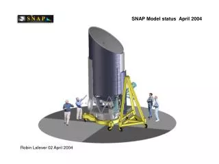
As-built 09 April 2008 RIGHT NOW, the Cuore experimental area is under construction. Many construction details are still being designed, Including clean room and Radon mitigation strategies. Timing may well limit the options being considered for the installation of a Radon barrier and clean room modificatios. Cuore concrete support structure with jack screws in place Cuore site with elevator deck ready for installation Robin Lafever CUORE Structure assembly sequence
Timing Build-up sequence Superimposing the CAD model illustrates how the build-up sequence has influenced the choices for an appropriate Radon barrier because of access and installation constraints Support structure with major structural elements in place, including the elevator deck Robin Lafever CUORE Structure assembly sequence
Timing Build-up sequence Continued At this point, the only options for installing a Radon barrier will be limited to the INSIDE surfaces of the clean room. Robin Lafever CUORE Structure assembly sequence
Timing Build-up sequence Continued Hut carpentry will probably precede clean room installation, But access to the clean room exterior is clearly restricted Robin Lafever CUORE Structure assembly sequence
Timing Clean Room idealized The electronics bay currently has no requirement for either particle count or Radon exclusion, but, further restrict access to the clean room roof. Robin Lafever CUORE Structure assembly sequence
Timing Clean Room idealized The current clean room geometry is shown here as an ‘ideal’ layout with no interfering structure around it. Assuming a Radon barrier is applied to the outer surfaces of the clean room, this is the time to do it. However, this is not a real possibility. Therefore, we must consider methods for installing a barrier before the clean room construction. Or, modifying the clean room panels such that they ARE the Radon barrier. Robin Lafever CUORE Structure assembly sequence
Radon-free strategies Radon Box The ‘Radon Box’ is a welded membrane which includes all air-handling and ductwork. The concept is to conserve and reuse Radon-free air and is sensitive to permeability and leaks. In conflict with minimum room air changes (5/hr) required for Clean Room operation. To realize this concept in our application requires reducing the Radon-free volumes into small zones and May require negotiated safety equipment and waivers. It will be expensive. All N2 Assumes all work is done under N2 with NO radon-free air supply. Preferred scenarios use soft enclosures and glove enclosures. Extreme scenarios involve working in N2 atmosphere with Oxygen masks Local Radon-free zones Uses temporary enclosures around work area supplied with Radon-free air. Depends on high flush rate in small volumes. Less sensitive to leaks and permeation. More sensitive to air exchange rates Robin Lafever LBNL, LNGS
Radon Box concept Robin Lafever
Radon Box concept Robin Lafever
Radon Barrier Zones Robin Lafever
Radon Box Zones Robin Lafever
Radon Box Zones Robin Lafever
Radon Box Zones Robin Lafever
Radon Box Zones Robin Lafever
Doors Robin Lafever
Doors Robin Lafever
300 K Flange modifications Robin Lafever
300 K Flange, MODIFIED In addition, feed-through assemblies are required for the Lifting assembly. The radial position and feed-through details are not known at the moment, but this treatment shows Radon Seals and cables inside the adapter flange. Robin Lafever
300 K Flange, MODIFIED Bottom view Note that the Suspension assemblies Are potential Radon leaks and need seals. The details are not known to me, however, I Show an assembly that could incorporate O-ring packing glands. Robin Lafever
Top section view showing Suspension hardware, Cable feed-throughs, and the adapter Flange with Radon Barrier/vibration isolator Note that the feed-through will need some radial space, TBD. Robin Lafever
Bottom section Again, note that the suspension Hardware needs a Radon seal Again, this is a potential Radon leak And will need some kind of seal. I do not know what the actual details are. Robin Lafever
Soft Enclosures Robin Lafever LBNL, LNGS