Download
1 / 41
410 likes | 530 Views
Autonomous Quadrocopter Proposal. Brad Bergerhouse, Nelson Gaske, Austin Wenzel Dr. Malinowski. Outline. Introduction Goals Project Description Tests Schedule. Outline. Introduction Goals Project Description Tests Schedule. What is a Quadrocopter?.

E N D
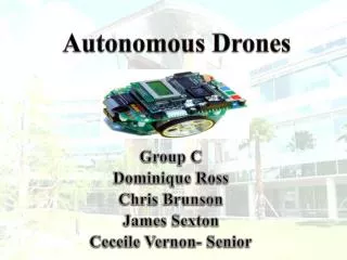
Autonomous Quadrocopter Proposal Brad Bergerhouse, Nelson Gaske, Austin Wenzel Dr. Malinowski
Outline • Introduction • Goals • Project Description • Tests • Schedule
Outline • Introduction • Goals • Project Description • Tests • Schedule
What is a Quadrocopter? • A quadrocopter is an aircraft that is lifted and propelled by four rotors.
Why is this technology important? • Quadrocopters are inherently stable platforms which share advantages with helicopters and airplanes, without the disadvantages • Microprocessor and DSP chip integration provides an powerful core while maintaining the low power usage of single chip processors
Why this project? • To develop an autonomous vehicle with 6-DOF • Tackle challenges presented during 3 dimensional navigation with minimal sensors • Provides a unique opportunity to implement an aerial platform for use in future department projects and courses
Outline • Introduction • Goals • Project Description • Tests • Schedule
Goals • Implement backup fly-by-wire controls for safety and testing • Avoid obstacles using video and sensor feedback • Autonomously navigate through narrow passages using onboard sensors • Develop a quadrocopter platform for future senior projects
Fly-by-wire • Remotely control quadrocopter with computer joystick or R/C transmitter for safety • Implemented to prevent loss of control during development and testing
Obstacle Avoidance • Use range sensors and single camera to avoid obstacles • Range sensors will be (initially) positioned in all 6 Euclidian directions • Camera will be aimed forward and DSP will be used for object detection
Autonomous Navigation • Navigate narrow passages in a fully autonomous nature • Create ‘obstacles’ using symbols to indicate directional constraints
Future Platform • Fully document design process and component interfacing • Expandable processing and I/O components
Outline • Introduction • Goals • Project Description • Tests • Schedule
Project Description • Interface BeagleBoardwith XAircraft X650 Quadrocopter platform • Use BeagleBoard I/O to interface with sensors and remote controls • Develop passage following algorithm using minimal sensor input • Utilize image processing techniques to detect obstacles or goal criteria
XAircraft X650 • Platform includes controllers, motors, and infrastructure required for operation • Accepts industry standard R/C PWM inputs for flight controller • Handles stability and individual motor control for arbitrary PWM inputs
BeagleBoard • Includes TI OMAP processor, USB interfaces and camera header • Performs processing required for navigation • Outputs industry standard PWM directly into flight controller
IR Distance Sensors • Output analog voltage based upon distance to an obstacle • Linear response between 10cm and 150cm • ADC necessary to interface with Beagleboard
TI ADC • 12-bit Octal ADC with I2C interface • Bridges logic between sensors and Beagleboard • 50K samples per second
Accelerometer • Possibly used for orientation input to BeagleBoard
I2C Interface • Inter-Integrated Circuit • Master-slave 2-wire bus interface • Used to communicate between ADC, Accelerometer, and BeagleBoard • Additional logic level converter required to interface between BeagleBoard (1.8V) and ADC (5V)
Camera • Captures images, send to BeagleBoard over serial communication • 5-Megapixel image output with downsizing for processing speed
Laptop • Communicates via 802.11 wireless protocol to BeagleBoard • Transmits manual override controls to Beagleboard • Provides goal conditions for navigation • Can act as a data store for retrieved information
DSP • Images processed using Canny edge detection algorithm • Symbol detection using predefined symbols for navigation control • Communicates with processor using shared memory regions
OMAP ARM core • Interprets sensor information • Provides control outputs to platform • Monitors sensor inputs for proper goal conditions
Outline • Introduction • Goals • Project Description • Tests • Schedule
Tests to be performed • Tethered Testing • Takeoff and Landing • Move at constant altitude to a landmark • Change altitude during flight, continue to landmark • Move in straight line through narrow passageway • Un-Tethered Testing • Fly straight and return to starting position • Fly through narrow passageway and turn corner
Outline • Introduction • Goals • Project Description • Tests • Schedule
Division of labor • Austin • DSP and object recognition • Brad • Communication and networking • Nelson • Hardware interfacing and power management
Schedule • 11/17-Camera and Joystick Interfacing • 12/1-Wireless and I2C interfacing • 1/19-PWM output design • 1/26-PWM output testing • 2/2-IR sensor interfacing • 2/9-Platform Assembly • 2/16-Platform Power Testing • 2/23-Initial Navigation Design
Schedule contd • 3/1-Navigation Design • 3/8-Navigation Design • 3/22-Navigation Design • 3/29-Test Design • 4/5-Testing and debugging • 4/12-Testing and debugging • 4/19-Testing and debugging • 4/26-Presentation preparation