Download
1 / 78
780 likes | 971 Views
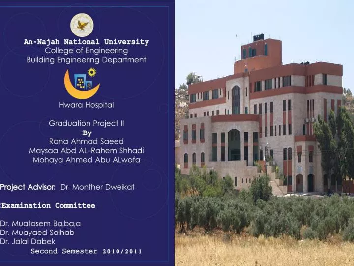
General Scope of Project Redesign of " Hewara Hospital“, which aimed to meet the needs of health services, surgery and particularly child services, for Huara region and villages around . Project Objective : Architectural ,structural ,environmental and mechanical redesign

E N D
General Scope of ProjectRedesign of " HewaraHospital“, which aimed to meet the needs of health services, surgery and particularly child services, for Huara region and villages around . Project Objective: Architectural ,structural ,environmental and mechanical redesign of Hewara hospital
:LocationLand for the project at Huara in Nablus , which is located in the north of West Bank
2 3 1 4 FIRST FLOOR
Arcitictural modifications 1- Anew staircase is added to the building for emergencies and special cases.
An elevator for dirty blanket to be washed in laundry hall is added to the building
The sixth modification is : An additional part was added to the second floor(( intensive care unit))
Design steps: • 1- Divide the building into two blocks. • Structural Design • 2- Preliminary Design. • 3- Computer modeling using SAP. • 4- Design the structural elements using SAP analysis results. • 5- Hand calculation to design other structural element (shear wall , • Retaining wall ,water tank).
Design codes The structural design will be according to : **ACI 318-08 (2008) (American Concrete Institute) code is used as a reference for design in our project. **UBC- 97( Uniform Building Code) is used to calculate the equivalent static force of the earthquake ** analysis and design are done using 3D model using SAP2000 program.
Project description: • Building consists of five stories as shown below :
Building is divided into two blocks using structural joints As shown below: Block 2 • Block 1
Preliminary Design: **Ribbed slab thickness The critical span length is 5.83 m (one-end continuous), and the required slab thickness is: h=Ln/18.5=5.83/18.5=0.31 m(one-end continuous). h≈ 0.3m Thus, ribbed slab of( 30) cm thickness is used shown : • ** Preliminarybeam dimensions • 1-For main beams: • hidden beam • h= 0.30 m • B=85 cm • 2-For secondary beams: • hidden beam • h= 0.30 m • B=70 cm
Structural analysis: ** analysis and design are done using SAP2000 program. Model Verification: compatibility check is achieved as shown below: 1-COMPATABILITY Check
As shown below there are some modes shapes with periods: a-Mode 1 with period = 0.69s b-Mode 2 with period = 0.6799s
3- INTERNAL FORCES CHECK *internal forces for beams ,slabs ,and columns For beams:
Design of structural elements using SAP analysis results: * Design will include the following elements : • 1) Beams ( main beam & secondary beam) . • 2) Columns . • 3) Floor systems [slabs ( one way rib slab)]. 4) Footings. 5) Shear walls. 6) Retaining walls. 7) Water tank. 8) Stairs.
Design of beams using SAP analysis results: Mu(-)ve =13.94t.m Mu(-)ve =18.74t.m Mu +ve =9.99t.m
Sample calculation to check B1 dimensions (hidden beam): 1- Design for positive moment: Mu +ve= 9.99 Ton.m OK • ρmax >ρ= 4.35×10⁻³ > ρmin As =ρ ×b × d = 4.35×10-3 ×110×24= 11.6 cm2 < As from SAP (14.48 cm2) 2- Design for negative moment at right side of beam: Mu (-)veat right side =13.94t.m • ρmax >ρ= 6.19×10⁻³ > ρmin OK As = 16.34 cm2 < As from SAP (21.43 cm2) 3- Design for negative moment at left side of beam Mu (-)ve =18.74t.m • ρmax >ρ= 8.5×10⁻³ > ρmin As =22.12cm2 < As from SAP (22.47 cm2) OK
Beams Reinforcement For exterior beams we use hooked bars Ld≥12 db
Detail A: Detail (B):
Plan for F1 reinforcement • section for F1 reinforcement with col.3
= • Design of Wall Footing • design of wall footing with 0.3 m thickness , 2 m width
Design of the walls: **Design of shear walls *Check shear • φ Vc1 =72.37 t • *Vu1 (sap) =28.2t < φVc1 OK • * φ Vc2=3.44 t >Vu2(SAP)=1.7 t OK *Check capacity φ Pn>Pu(sap) OK • Steel in horizontal direction: • As=0.002×100×25= 4.0 cm2 • use 1 ф10/20cm tow layer • Steel in vertical direction : • As=0.0014* 100*25cm2 • use 1ф12/25cm tow layer.
**Design of retaining walls • *Wall reinforcement Vertical steel • As =2505 m² • Use ϕ 18 • N =10 bars • S =100 cm • Use 100 mm use 1ϕ18 /100mm • Shrinkage steel • As min = 0.003 *b *h=900 mm² /m • N= 4 bars/m • Use 1ϕ18 /250mm weights on retaining wall
Design of base (h=40cm) *Design of toe • *Toe reinforcement Mu =15.05 KN.m • As=120.9 cm² • Use Asmin =0.0018 *1000 *400 =720 mm²/m Assume ϕ 14 ,N =5 Use 1ϕ14 /200mm Shrinkage for toe: Use1ϕ14 /200mm • Soil weights &soil pressure on toe
*Design of heel • *Heel reinforcement Mu =18.47 KN.m • As= 148.5 mm²Use Asmin=720 mm²/m Assume ϕ 14 ,N =5 Use 1ϕ14 /200mm Shrinkage for toe: Use1ϕ14 /200mm • Soil weights &soil pressure on heel
Design of water tank • Vertical steel • use1φ 25 /150 mm • Use 1φ20 /500 mm • Check minimum steel • Vertical steel • As shrinkage =0.003*bh=1500 mm²/m • horizontal steel • Horizontal steel • As shrinkage =0.005*bh=2500mm²/m Detail for reinforcement the water tank
Seismic Design seismic analysis for region:City name: Nablus.Area Name: HewaraZone: 2BZ = 0.20 0.24=Ca 0.32=Cv
Climate temperature In summer the temperature reaches 31.9 C 0 and in winter reaches 5.7C 0 • Rain : Limited to winter and autumn- 80% of rainfall is in the period between the months of December first and March Moisture : Summer: 61.9% iWinter reach to 69.7% Wind: • Prevail in the Nablus area two types of winds are south-western and north-west, where the annual rate up to the wind speed to 4.7km per hour