Download

1 / 35
350 likes | 575 Views
UNIT – IV INTERNAL COMBUSTION ENGINES. Engines. The distinctive feature of our civilization today, one that makes it different from all others, is the wide use of mechanical power.

E N D
UNIT – IV INTERNAL COMBUSTION ENGINES
Engines • The distinctive feature of our civilization today, one that makes it different from all others, is the wide use of mechanical power. • At one time, the primary source of power for the work of peace or war was chiefly man’s muscles. Later, animals were trained to help and afterwards the wind and the running stream were harnessed. • But, the great step was taken in this direction when man leaned the art of energy conversion from one form to another form. The machine which does this job of energy conversion is called an Engine.
Very first trains pulled by horses DIESEL LOCO STEAM ENGINE
Components/ Definitions • Top Dead Center (TDC): The piston is at its highest point in the cylinder. • Bottom Dead Center (BDC): The piston is at its lowest point in the cylinder. • Bore (D): Diameter of the cylinder • Stroke (L) : A stroke is a single transverse of the cylinder by the piston.(From TDC to BDC) 1 revolution of crankshaft = 2 stroke of piston • Compression ratio (r): It is the comparison of the cylinder volume when the piston is at BDC and the volume when piston is at TDC. In other words it is defined as the ratio between total volume and clearance volume of the cylinder.
ANIMATION – IC ENGINES http://www.animatedpiston.com/TwinCam.htm http://www.animatedengines.com/otto.shtml http://www.howstuffworks.com/engine1.htm
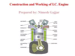
Construction details • Cylinder Block: It is the center part of engine frame that contains cylinders in which piston moves and support cylinder liners and head. • Cylinder head : It is the cover of cylinder block and support valve trains. It is used to admit, confine and release fuel and air. • Crank case: It is the bottom of engine frame section that houses the crank shaft. • Piston: It is the inner parts of cylinder which reciprocate upward and downward by combustion of gases. • Piston rings: There are two types of rings provided in the outer parts of piston such as • Compression ring which is used to avoid leakage of burnt gases from top of piston to bottom. • Oil ring which used to avoid splitting lubricating oil from crank case to top of piston
Construction details • Connecting rod: It is the part connects the piston and crank shaft. It is used to convert the reciprocating motion into rotary motion. • Crank shaft: It is the output shaft, from where power is transferred to transmission line in vehicle. It drives camshaft, generator, pumps etc. • Flywheel: It is connected to crankshaft which absorbs and releases kinetic energy of piston strokes and smoothes rotation of crankshaft. • Valves: There are two valves in each cylinder head such as intake valve which is used to open to admit air to cylinder (with fuel in petrol engine) and exhaust valve which is used to open to allow gases to be rejected outside. • Cam shaft and cams: It is used to actuate the intake and exhaust valves through push rods and rocker arm.
Working Principle of IC Engines: • Nicolas A. Otto invented the petrol engine. This engine is working on Otto cycle. Fuel is ignited by using spark plug so it is also called as spark ignition engine. • The cycle of operations is completed in four strokes of the piston or two revolutions of the crank shaft. During the four strokes, there are five events to be completed, such as suction, compression, expansion or power, and exhaust. • Each stroke consists of 180 of crank shaft rotation and hence a four stroke cycle completed through 720 of crank rotation. The carburetor and ignition system are necessary.
Suction or Intake Stroke • Suction stroke starts when piston is at top dead center and about to move downwards. • The inlet valve is open at this time and the exhaust valve is closed. • Due to the suction created by the motion of the piston towards the bottom dead center, the charge consisting of fuel air mixture is drawn into the cylinder. • When the piston reaches the bottom dead center the suction stroke ends and the inlet valve closes.
Compression Stroke • The charge taken into the cylinder during the suction stroke is compressed by the return stroke of the piston. • During this stroke both inlet and exhaust valves are in closed position. The mixture which fills the entire cylinder volume is now compressed into the clearance volume. • At the end of the compression stroke the mixture is ignited with the help of a spark plug located on the cylinder head. During the burning process the chemical energy of the fuel is converted into heat energy. • The pressure at the end of the combustion process is considerably increased due to heat from the fuel.
Expansion or Power Stroke • The high pressure of the burnt gases forces the piston towards the BDC, both the valves are in closed position. Of the four strokes only during this stroke power is produced. • Both pressure and temperature decrease during expansion.
Exhaust Stroke • At the end of the expansion stroke the exhaust valve opens and the inlet valve remains closed. • The pressure falls to atmospheric level a part of the burnt gases escape. • The piston starts moving from the bottom dead center to top dead center and sweeps the burnt gases out from the cylinder almost at atmospheric pressure. • The exhaust valve closes when the piston reaches TDC.
Four Stroke Diesel Engines • Diesel Engine was invented by Rudolph Diesel. It is ignited by compression of gas so it’s also called as compression ignition engine. • It is similar to four stroke petrol engine but operates at a much higher compression ratio. The compression ratio of an SI engine is between 6 and 10 while for a CI engine it is from 16 to 20. • In suction stroke only air is inducted into the cylinder. A high pressure fuel pump and an injector are provided to inject the fuel into the combustion chamber.
Suction Stroke: • Suction stroke starts when piston is at top dead center and about to move downwards. • The inlet valve is open at this time and the exhaust valve is closed. • Due to the suction created by the motion of the piston towards the BDC, Air alone is inducted during the suction stroke.
Compression Stroke • Air inducted during the suction stroke is compressed into the clearance volume due to return stroke of piston. • Both valves remain closed during this stroke. • The air in the combustion chamber is at high temperature and high pressure with a decrease in volume.
Expansion Stroke or Power Stroke: • At the end of compression stroke, the fuel is injected into the cylinder in the form of fine spray through the nozzle and is ignited by the temperature of hot compressed air in the chamber. • So that combustion process is started at the end of this stroke. • The combustion of gases expands inside the cylinder so that piston start to move towards BDC. • Both the valves remain closed during this stroke
Exhaust Stroke: • The piston traveling from BDC to TDC pushes out the product of combustion. • The exhaust valve is open and the intake valve is closed during this stroke.
Two Stroke Cycle Petrol Engine • A two-stroke cycle-petrol engine was devised by Duglad Clerk in 1880. • In this Cycle, the suction, compression, expansion and exhaust takes place during two strokes of the piston. • It means that there is one working stroke after every revolution of the crank shaft. • A two stroke engine has ports instead of valves
Suction Stage: • In this stage, the piston, while going down towards BDC, uncovers both the transfer port and the exhaust port. • The fresh fuel-air mixture flows into the engine cylinder from the crank case, as shown in the figure below.
Compression Stage: • In this stage, the piston, while moving up, first covers the transfer port and then exhausts port. • After that the fuel is compressed as the piston moves upwards as shown in the figure. • In this stage, the inlet port opens and fresh fuel-air mixture enters into the crank case.
Expansion Stage: • Shortly before this piston reaches the TDC (during compression stroke), the charge is ignited with the help of a spark plug. • It suddenly increases the pressure and temperature of the products of combustion. But the volume, practically, remains constant. Due to rise in the pressure, the piston is pushed downwards with a great force as shown in the figure. • The hot burnt gases expand due to high speed of the piston. During this expansion, some of the heat energy produced is transformed into mechanical work.
Exhaust Stage • In this stage, the exhaust port is opened as the piston moves downwards. • The products of combustion, from the engine cylinder are exhausted through the exhaust port into the atmosphere, as shown in the Figure. • This completes the cycle and the engine cylinder is ready to suck the charge again.
Animation for 4 – Stroke engine: http://www.k-wz.de/vmotor/v_omotore.html