Download
1 / 42
810 likes | 2.4k Views
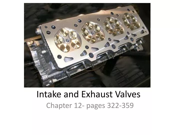
Intake and Exhaust Valves. Chapter 12- pages 322-359. Cylinder Head Construction. This cast iron or aluminum head has two-valve combustion chambers – some 3, 4 or 5 valves Bolts to the deck of the cylinder block Covers and encloses the top of the cylinders

E N D
Intake and Exhaust Valves Chapter 12- pages 322-359
Cylinder Head Construction This cast iron or aluminum head has two-valve combustion chambers – some 3, 4 or 5 valves • Bolts to the deck of the cylinder block • Covers and encloses the top of the cylinders • Combustion chambers are small pockets formed in the cylinder head • combustion occurs in these small pockets
Cylinder Head Combustion chambers contain the spark plug tip and valve seats • Intake ports • route air (diesel engine) or air and fuel (gasoline engine) into the combustion chamber • Exhaust ports • route burned gases out of the combustion chamber • Valve guides • small holes machined through the cylinder head for the valves • valves slide in these guides • Valve seats • machined surfaces in the combustion chamber port openings
Cylinder Head Parts When the valve is closed, it sealsagainst the valve seat
Valve Construction • Automotive engines commonly use poppet valves – special hardened steel or stainless • Some valve stems are chrome plated to better resist wear – titanium also (for heat - weight) • Grooves are cut into the valve stem tops for the keepers – valve face contacts seat • Valves operate very hot (1,500 to 4,000 deg.) and need to cool – through valve stem and seat (when closed)
Valve Tip Valve Keeper Grooves Stem Valve head Face Margin Parts of a valve Fillet
Valves Open and close the ports inthe cylinder head
Valve Construction A. Polished intake valve B. Stock exhaust valve C. Hollow exhaust valve is filled with sodium for cooling D. Intake is usually has a larger head
Sodium-Filled Valves • Used when extra valve cooling action is needed • During operation, the sodium inside the hollow valve melts, becoming a liquid • This liquid is used to cool the valve
Sodium-Filled Valves • When the valve is opened, the sodium splashes down into the head and collects heat • When the valve is closed, the sodium splashes up into the stem • Heat transfers out of the sodium and into the stem, valve guide, and engine coolant • NEVER cut into valve stem and release sodium – burns when hits water
Stellite Valve Stellite coating on its face retards wear and allows the use of unleaded gasoline
Valve Guide Construction • There are two basic types of valve guides: • integral valve guides • pressed-in valve guides • Critical to remove heat • Wears in direction of rocker • Excessive clearance causes oil consumption • Valve contact area is determined by guide
Integral Valve Guide • Part of the cylinder head casting • Simply a hole machined through the cylinder head • Very common because of its low production cost • Can be repaired by knurling
Pressed-In Valve Guide • Separate sleeve forced into a hole machined in the cylinder head • Made of cast iron or bronze • During repair, a worn guide can be pressed out and a new guide can be quickly pressed in
Valve Seat Angle • Angle formed by the face of the seat in the head • Most engines use a 45º angle • Some high-performance engines use seat angles of 30º • High performance valve cut will use 3 different degrees (3 angle valve job) to increase flow
Valve Face Angle • Angle on face • Angle formed between the valve face and valve head • Normal valve face angles are 45º and 30º
Valve Seat Angle An interference angle increases sealing pressure and speeds seating
Valve Seals Prevent oil from entering the combustion chambers through the valve guides
Umbrella Valve Seal • Shaped like a cup • Made of neoprene rubber or plastic – may have spring to seal tighter • Slides down over the valve stem before the spring and retainer • Covers the small clearance between the valve stem and guide • Keeps oil from being drawn into the cylinder head port and combustion chamber
Umbrella Valve Seal A. Synthetic rubber seal with plastic shedder insert B. All synthetic rubber seal C. Plastic valve seal
O-Ring Valve Seal • Small round seal that fits into an extra groove cut in the valve stem • Seals the gap between the retainer and valve stem • Stops oil from flowing though the retainer, down the stem, and into the guide • Fits onto the valve stem after the spring and retainer
Nylon Shedder Used to limit the amount of oil that splashes on the valve stem
Valve Spring Assembly Used to close the valve
Valve Spring Construction This dual coil spring is designed toincrease spring pressure
Valve Spring Terminology • Spring tension • stiffness of a valve spring • service manual will give the tension in pounds or kilograms for specific compressed lengths • Spring free length • length of the spring when removed from the engine • Spring must be straight – not warped • Note if spring is wound different at top • Flat spring called damper spring – controls vibrations
Valve Spring Shim • Very thin, accurately machined washer used to increase spring tension • When a shim is placed under a spring, the open and closed lengths of the spring are reduced • Provides a means of restoring full spring pressure without spring replacement
Valve Retainers and Keepers Used to lock the valve springonto the valve
Valve Spring Seat • Cup-shaped washer installed between the cylinder head and the bottom of the valve spring • Provides a pocket to hold the bottom of the valve spring
Valve Rotators • Turn the valves to prevent carbon buildup and hot spots on the valve faces • May be located under or on top of the valve spring • Commonly used on exhaust valves, which are exposed to more heat than intake valves
Valve Rotators This engine uses a valve rotator for each exhaust valve
Valve Rotators This engine uses a valve rotatorfor each valve
Valve Stem Cap • Must be flat – not worn • Outer edge should be angled slightly • If you remove material from valve face– need to tip valve to correct installed height
Valve Stem Cap • May be placed over the end of the valve stem • Helps prevent stem and rocker arm wear • Free to turn on the valve stem • Serves as a bearing that reduces friction • May be used to adjust clearance in the valve train
Valvetrain Components • Pushrods • Normally found in OHV engines when camshaft is located in the block. • Connecting link between the camshaft/follower and the rocker arm. • Hollow pushrods are used to pass oil from hydraulic lifters to the rocker arm assy.
Diesel Prechamber Cup • Pressed into the cylinder head of some diesel engines • Holes are machined into the deck • Prechambers are force-fit into these holes • Each prechamber forms an enclosure around the tip of an injector and glow plug
Diesel Prechamber Cup Area is heated by the glow plug forbetter cold starting
Stratified Charge Chamber • Fits into the cylinder head casting to form an auxiliary chamber • Uses a rich fuel mixture in the auxiliary chamber to ignite a lean mixture in the main combustion chamber • May use another intake valve to introduce air/fuel charge into chamber
Items to check during overhaul • Check stem for wear – measure margin • Check guide for wear • Check specification for clearance • Check valve face contact area with machinists blue • Lap valves in with paste and suction cup • Check valve installed height • Check springs • Can replace valve seals while head is on engine