Download
1 / 46
460 likes | 631 Views

E N D
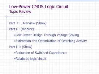
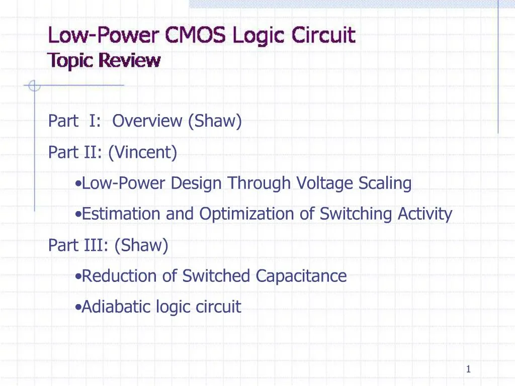
1. 1
2. 2
3. 3 For high performance digital systems:
The common traits of high-performance chips are the high integration density and the high clock frequency. The power dissipation of the chip becomes temperature increased with the increasing clock frequency. Since the dissipated heat must be removed effectively to keep the chip temperature at an acceptable level, the cost of packaging, cooling, and heat removal becomes a significant factor in these circuits. Several high-performance microprocessor chips designed in the early 1990�s (e.g., Intel Pentium, DEC Alpha, and PowerPC) operated at clock frequencies in the range of 100 to 300 MHz, and their typical power consumption was between 20 to 50 W. Modern microprocessors are running at clock frequencies above 1 GHz with 100 W power dissipation.
For reliability:
There is a close correlation between the peak power dissipation of digital circuits and reliability problems such as electro-migration and hot-carrier induced device degradation.
For high performance digital systems:
The common traits of high-performance chips are the high integration density and the high clock frequency. The power dissipation of the chip becomes temperature increased with the increasing clock frequency. Since the dissipated heat must be removed effectively to keep the chip temperature at an acceptable level, the cost of packaging, cooling, and heat removal becomes a significant factor in these circuits. Several high-performance microprocessor chips designed in the early 1990�s (e.g., Intel Pentium, DEC Alpha, and PowerPC) operated at clock frequencies in the range of 100 to 300 MHz, and their typical power consumption was between 20 to 50 W. Modern microprocessors are running at clock frequencies above 1 GHz with 100 W power dissipation.
For reliability:
There is a close correlation between the peak power dissipation of digital circuits and reliability problems such as electro-migration and hot-carrier induced device degradation.
4. 4
5. 5
6. 6
7. 7
8. 8 Alpha T: effective number of power-consuming voltage transitions experienced per clock cycle.Alpha T: effective number of power-consuming voltage transitions experienced per clock cycle.
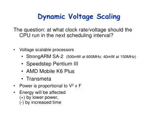
9. 9 Several different means for reducing the power consumption. These measures include: 1. Reduction of the power supply voltage VDD. 2. Reduction of the voltage swing in all nodes. 3. Reduction of the switching probability (transition factor) 4. Reduction of the load capacitance.
Several different means for reducing the power consumption. These measures include: 1. Reduction of the power supply voltage VDD. 2. Reduction of the voltage swing in all nodes. 3. Reduction of the switching probability (transition factor) 4. Reduction of the load capacitance.
10. 10
11. 11 If a CMOS inverter (or a logic gate) is driven with input voltage waveforms with finite rise and fall times, both the nMOS and pMOS transistors in the circuit may conduct simultaneously for a short amount of time during switching, form a current path between the power supply and the ground.
This current does not contribute to the charging of the capacitances in the circuit, and hence, it is called the short-circuit current component.If a CMOS inverter (or a logic gate) is driven with input voltage waveforms with finite rise and fall times, both the nMOS and pMOS transistors in the circuit may conduct simultaneously for a short amount of time during switching, form a current path between the power supply and the ground.
This current does not contribute to the charging of the capacitances in the circuit, and hence, it is called the short-circuit current component.
12. 12
13. 13 The reason is that pMOS transistor remains in saturation during the entire input transition, as opposed to the previous case where the transistor leaves the saturation region before the input transition is completed.The reason is that pMOS transistor remains in saturation during the entire input transition, as opposed to the previous case where the transistor leaves the saturation region before the input transition is completed.
14. 14 Consider a CMOS inverter with a high input voltage, where the nMOS transistor is turned on and the output node voltage is discharged to zero. Although the pMOS transistor is turned off, there will be a reverse potential difference of Vdd between its drain and the n-well, causing a diode leakage through the drain junction. The n-well region of the pMOS transistor is also reverse-biased with Vdd, with respect to the p-type substrate. Therefore, another significant leakage current component exists because of the n-well junction.Consider a CMOS inverter with a high input voltage, where the nMOS transistor is turned on and the output node voltage is discharged to zero. Although the pMOS transistor is turned off, there will be a reverse potential difference of Vdd between its drain and the n-well, causing a diode leakage through the drain junction. The n-well region of the pMOS transistor is also reverse-biased with Vdd, with respect to the p-type substrate. Therefore, another significant leakage current component exists because of the n-well junction.
15. 15 Note that the reverse leakage occurs even during the stand-by operation when no switching takes place. Hence, the power dissipation due to this mechanism can be significant in a large chip containing several million transistors.Note that the reverse leakage occurs even during the stand-by operation when no switching takes place. Hence, the power dissipation due to this mechanism can be significant in a large chip containing several million transistors.
16. 16 Subthreshold current is due to carrier diffusion between the source and drain regions of the transistor in weak inversion. The subthreshold current exhibits an exponential dependence on the gate voltage. The amount of the subthreshold current may become significant when the gate-to-source voltage is smaller than, but very close to, the threshold voltage of the device. In this case, the power dissipation due to subthreshold leakage can become comparable in magnitude to the switching power dissipation of the circuit.
Note that subthreshold current can occur even there is no switching activity in the circuit and that this component must be carefully considered for estimate the total power dissipation.
Note that the subthreshold leakage current can occur even when there is no switching activity in the circuit and that this component must be carefully considered for estimating the total power dissipation in the stand-by operation mode.
One relatively simple measure to limit the subthreshold current component is to avoid very low threshold voltage, so that the Vgs of the nMOS transistor remains safely below Vt,n when the input is logic zero, and the Vgs of pMOS transistor remains safely below Vt,p when the input is logic one.Subthreshold current is due to carrier diffusion between the source and drain regions of the transistor in weak inversion. The subthreshold current exhibits an exponential dependence on the gate voltage. The amount of the subthreshold current may become significant when the gate-to-source voltage is smaller than, but very close to, the threshold voltage of the device. In this case, the power dissipation due to subthreshold leakage can become comparable in magnitude to the switching power dissipation of the circuit.
Note that subthreshold current can occur even there is no switching activity in the circuit and that this component must be carefully considered for estimate the total power dissipation.
Note that the subthreshold leakage current can occur even when there is no switching activity in the circuit and that this component must be carefully considered for estimating the total power dissipation in the stand-by operation mode.
One relatively simple measure to limit the subthreshold current component is to avoid very low threshold voltage, so that the Vgs of the nMOS transistor remains safely below Vt,n when the input is logic zero, and the Vgs of pMOS transistor remains safely below Vt,p when the input is logic one.
17. 17
18. 18
19. 19
20. 20
21. 21
22. 22
23. 23
24. 24
25. 25
26. 26 The dissipated energy is smaller than for the conventional case if the charging time is greater than 2RC. In fact, the dissipated energy can be made arbitrarily small by increasing the charging time, since Ediss is inversely proportional to T. Also, we observe that the dissipated energy is proportional to the resistance R, as opposed to the conventional case where the dissipation depends on the capacitance and the voltage swing. Reducing the on-resistance of the pMOS network will reduce the energy dissipation.
We have seen that the constant-current charging process efficiently transfers energy from the power supply to the load capacitance. A portion of the energy thus stored in the capacitance can also be reclaimed by reversing the current source direction, allowing the charge to be the adiabatic operation, since in conventional CMOS circuit the energy is dissipated after being used only once. The constant current power supply must certainly be capable of retrieving the energy back from the circuit. Adiabatic logic circuits thus require non-standard power supplies with time-varying voltage, also called pulsed-power supplies. The additional hardware overhead associated with these specific power supply circuits is one of the design trade-offs that must be consider when using the adiabatic logic.
The dissipated energy is smaller than for the conventional case if the charging time is greater than 2RC. In fact, the dissipated energy can be made arbitrarily small by increasing the charging time, since Ediss is inversely proportional to T. Also, we observe that the dissipated energy is proportional to the resistance R, as opposed to the conventional case where the dissipation depends on the capacitance and the voltage swing. Reducing the on-resistance of the pMOS network will reduce the energy dissipation.
We have seen that the constant-current charging process efficiently transfers energy from the power supply to the load capacitance. A portion of the energy thus stored in the capacitance can also be reclaimed by reversing the current source direction, allowing the charge to be the adiabatic operation, since in conventional CMOS circuit the energy is dissipated after being used only once. The constant current power supply must certainly be capable of retrieving the energy back from the circuit. Adiabatic logic circuits thus require non-standard power supplies with time-varying voltage, also called pulsed-power supplies. The additional hardware overhead associated with these specific power supply circuits is one of the design trade-offs that must be consider when using the adiabatic logic.
27. 27
28. 28
29. 29
30. 30
31. 31
32. 32
33. 33 The load capacitance is charged up by connecting the constant voltage sources V1 through VN to the load successively, using an array of switch devices. To discharge the load capacitance, the constant voltage sources are connected to the load in the reverse sequence.The load capacitance is charged up by connecting the constant voltage sources V1 through VN to the load successively, using an array of switch devices. To discharge the load capacitance, the constant voltage sources are connected to the load in the reverse sequence.
34. 34
35. 35
36. 36 The circuit uses differential logic, so each gate computes both a logic function and its complement, and each input to a gate requires both polarities to be represented. Each Nfet input gets the corresponding positive and negative polarity inputs and the cross-coupled Pfets are connected to the clock-supply. The circuit uses differential logic, so each gate computes both a logic function and its complement, and each input to a gate requires both polarities to be represented. Each Nfet input gets the corresponding positive and negative polarity inputs and the cross-coupled Pfets are connected to the clock-supply.
37. 37
38. 38
39. 39
40. 40 The primary advantage of 2N-2N2P over 2N2P is that the addition of the cross-coupled Nfets results in non-floating data valid over 100% of the HOLD phase, as opposed to 2N2P where, because the inputs are ramping down during the HOLD phase, a gates low output is only clamped for the first 50% of the HOLD phase.
The primary advantage of 2N-2N2P over 2N2P is that the addition of the cross-coupled Nfets results in non-floating data valid over 100% of the HOLD phase, as opposed to 2N2P where, because the inputs are ramping down during the HOLD phase, a gates low output is only clamped for the first 50% of the HOLD phase.
41. 41
42. 42
43. 43
44. 44
45. 45
46. 46