Download
1 / 22
260 likes | 520 Views
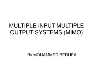
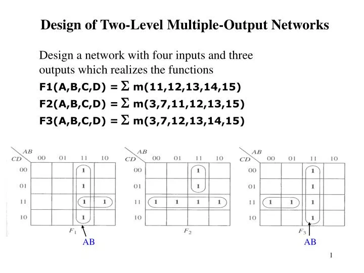
Design of Two-Level Multiple-Output Networks. Design a network with four inputs and three outputs which realizes the functions F1(A,B,C,D) = S m(11,12,13,14,15) F2(A,B,C,D) = S m(3,7,11,12,13,15) F3(A,B,C,D) = S m(3,7,12,13,14,15). AB. AB. Direct Realization (each function as a min.

E N D
Design of Two-Level Multiple-Output Networks Design a network with four inputs and three outputs which realizes the functions F1(A,B,C,D) =S m(11,12,13,14,15) F2(A,B,C,D) =S m(3,7,11,12,13,15) F3(A,B,C,D) =S m(3,7,12,13,14,15) AB AB
Direct Realization (each function as a min. sum of prime implicants) Note: AB is common to F1, F3 Multiple-Output Realization = AB+ACD = ABC’+A’CD+ACD = A’CD+AB
Example: Using Common Terms in Multiple Output Network Design f1 = a’bd + abd+ab’c’ + b’c f2 = c + a’bd f3 = bc + ab’c’ + abd 8 gates, 22 gate inputs
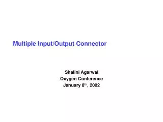
Another Example Best Soln. Soln. Requires extra gate
Another Example Soln. with max. number of common terms (8 gates, 26 inputs) Best Soln.has no common terms (7 gates, 18 inputs)
Code Converters • Code converters – take an input code, translate to its equivalent output code. Code converter Input code Output code • Example: BCD to Excess-3 Code Converter. Input: BCD digit Output: Excess-3 digit
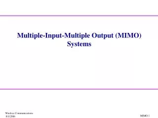
BCD-to-Excess-3 Code Converter W =Sm(5,6,7,8,9) • Truth table: x =S m(1,2,3,4,9) y =S m(0,3,4,7,8) z =S m(0,2,4,6,8)
AB AB 00 01 11 10 00 01 11 10 CD CD 00 x 1 00 1 x 0 0 4 8 12 0 4 8 12 01 1 x 1 01 1 x 1 9 1 5 13 9 1 5 13 11 1 x x 11 1 x x 11 3 15 7 11 3 15 7 10 1 x x 10 1 x x 14 2 6 10 14 10 2 6 AB AB 00 01 11 10 00 01 11 10 CD CD 1 00 1 x 1 00 1 1 x 1 0 4 8 0 12 4 8 12 01 01 x x 9 1 5 9 13 1 5 13 11 11 1 1 x x x x 11 11 3 15 7 3 15 7 10 x x 10 1 1 x x 14 2 6 10 14 2 6 10 x =Sm(1,2,3,4,9)+ Sd(10,11,12,13,14,15) bc’d’+b’d+b’c=bc’d’+b’(c+d) W = Sm(5,6,7,8,9)+ Sd(10,11,12,13,14,15) = a+bc+bd = a+b(c+d) Underlined terms are common y = Sm(0,3,4,7,8)+ Sd(10,11,12,13,14,15) = c’d’+cd z = Sm(0,2,4,6,8)+ Sd(10,11,12,13,14,15) = d’
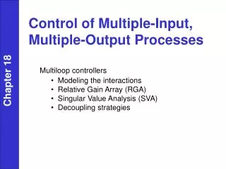
Multi-Output NAND and NOR Networks Conversion to a network of all NAND or all NOR gates can also be done for the case of multiple-output networks, using method of Section 8.6, p. 194 (a) Network of AND and OR gates (b) NOR network
Multiplexers 2/1 Multiplexer (MUX) I0 if S = 0, then Z = I0 if S = 1, then Z = I1 Data Inputs Z I1 S Logic Diagram I0 Control Input S’ Z S is the Control Input used to select one of the data inputs I0 ,I1 and connect it to the output terminal, Z. I1 S Z = I0S’ + I1S
Higher Order Muxes 4/1 Mux 8/1 Mux I0 I0 I1 I1 Z I2 I2 I3 Z I3 S1 S0 I4 I5 I6 if S = “00”, then Z = I0if S = “01”, then Z = I1 if S = “10”, then Z = I2if S = “11”, then Z = I3 I7 S[2:0] 3 Z = I0 S1’ S0’ + I1 S1’ S0 + I2 S1 S0’ + I3 S1 S0 Note: S[2:0] means the three control inputs S2 S1 S0 <--lsb
I0 Muxes are often used to select groups of bits arranged in busses. A0 I1 B0 Z Z0 S S I0 A1 I1 Z Z1 B1 A[3:0] S I0 D[3:0] Z B[3:0] I0 A2 I1 Z2 Z I1 S B2 S To build a 2/1 mux for 4-bit wide busses, need four 1-bit 2/1 muxes. I0 A3 Z3 I1 Z B3 S
Function Realization using MUX A 4-to-1 MUX can realize any 3-variable function with no added Logic gates. Example: Realize F(A,B,C)= A’B’ + AC Soln.: Expanding F so that all terms include both control inputs, A and B, yields F = A’B’ + AC(B’+B) = A’B’1 + AB’C + ABC The general eqn. For 4-to-1 MUX is F = A’B’I0 + A’BI1+ AB’I2+ ABI3 Comparing eqns. We see they will be identical if I0 =1, I1 =0, I2 =C, I3 =C
Function Realization using MUX Example: Consider the function Z(A,B,C,D) = Sm(0,1,3,6,7,8,11,12,14) and implement it using an 8-to-1MUX Soln.: Assume that A,B,C are applied to control inputs s2,s1,s0 resp. Then all 16 possible minterms that can be generated by the MUX can be represented in a table. I0 I1 I2 I3 I4 I5 I6 I7 000 001 010 011 100 101 110 111 D’ 0 2 4 6 8 10 12 14 D 1 3 5 7 9 11 13 15 1 D 0 1 D’ D D’ D’ Working out the bottom row tells us what to apply to I0, I1, 12, etc. How to work it out? e.g. I0 col D’+D=1, I1 col only minterm with D appears, (apply D), I2 col no minterms used (apply 0), I3 col D’+D=1, I4 col. only minterm with D’ appears(apply D’).
Example: Continued The function is then realized with an 8-to-1 MUX with ABC applied to the control inputs and the values found in the table to I0, I1, I2, etc. S1 S0 S2
Example: Continued Alternate Solution One-variable k-maps Represent all of the minterms of Z on a k-map. Then obtain groupings corresponding to [I0 = 000 with both D’ and D] [I1=001 with both D’ and D] etc. Each of the two-minterm groupings can be thought of as a 1-variable k-map in D only and simplified.
Example: Continued Yet anotherAlternate Solution This time assumethat A,B,D are applied to control inputs S2,S1,S0 resp. I0 I1 I2 I3 I4 I5 I6 I7 000 001 010 011 100 101 110 111 C’ 0 1 4 5 8 9 12 13 C’ C 2 3 6 7 10 11 14 15 1 C’ 1 C C C’ C 1 0 C C C’ C 1 S1 S2 0 S0 D Mux Realization with Control Inputs A, B, and D
Example: Continued Yet anotherAlternate Solution using external gates I0 I1 I2 I3 CD 00 01 10 11 Table method in this case is equivalent to four 2-variable K-maps 00 0 4 8 12 01 1 5 9 13 11 3 7 11 15 10 2 6 10 14
Decoders Exactly one of the output lines will be 1 for each combination of the input variables. This decoder generates all minterms of of the three input variables
Decoders 7442 4-to-10 decoder Note: Active low outputs
Realization of Multiple-Output Network using Decoder f1 = (m1’m2’m4’)’ = m1 +m2 +m4 f2 = (m4’m7’m9’)’ =m4 +m7 +m9 Can realize a function by ORing together selected minterm outputs. In this case outputs are active low, so NAND gates are used (effectively ORing together these outputs).