Download
1 / 28
280 likes | 429 Views
Status on HL-LHC heating. B. Salvant for the impedance team Many thanks to: Gianluigi Arduini, David Belohrad , Riccardo de Maria, Stephane Fartoukh, Giovanni Iadarola, Thibaut Lefevre, Elias Metral, Nicolas Mounet, Giovanni Rumolo, Ralph Steinhagen , Simon White, Carlo Zannini.

E N D
Status on HL-LHC heating B. Salvant for the impedance team Many thanks to: Gianluigi Arduini, David Belohrad, Riccardo de Maria, Stephane Fartoukh, Giovanni Iadarola, Thibaut Lefevre, Elias Metral, Nicolas Mounet, Giovanni Rumolo, Ralph Steinhagen, Simon White, Carlo Zannini. HL-LHC WP2 task leader meeting - October 19th 2013
Agenda • Beam spectra for 800 MHz? • Scaling to PIC1, PIC2, US1, US2 • Potential issues for hardware (difficult to predict)
bunch flattening of the LHC beam at 7 TeV(ESME Simulations) C. Bhat 2009 Vrf(400MHz)=16MV + Vrf(800MHz)=8.5MV Vrf(400MHz)=16MV Normal Bunch Flattened Bunch Mountain Range E vs t E vs t 2.5 eVs Line charge Distribution Line charge Distribution RMS Bunch Length vs Time lb=41cm z=7.5cm Energy Distribution Energy Distribution RMS Energy Spread vs Time E=2.6GeV rms=0.6GeV E=3.2GeV rms=0.72GeV Chandra Bhat
Bunch with 800 MHz Vrf(400MHz)=16MV + Vrf(800MHz)=8.5MV Flat bunches (C. Bhat, 2009) quotedby F. Zimmermann and S. Fartoukh Function proposed by Elena: Rho=exp(-t4/(2*sig4)) with sig=0.45 ns Function proposed by Stephane: Rho=(1+erf(4*(1-abs(t)/0.5e-9)))/2 With fitted parameters to the curve obtained in ESME
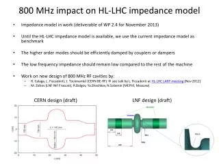
Power spectra (4*rms=1 ns) (4*rms=1 ns) (4*rms=1 ns) (4*rms=1.24 ns) (4*rms=1.2 ns) Flat bunches excite less power below 1.1 GHz, but more above
Power spectra (4*rms=1.15 ns) (4*rms=1.15 ns) (4*rms=1 ns) (4*rms=1.25 ns) (4*rms=1.2 ns) Flat bunches have less power below 1.1 GHz, but more above (also measured during MD on 28 Nov 2012)
Power loss dependence on various bunch distributions? Flat bunches not far from single RF situation in terms of heating for very broadband impedances (constant over frequency). Effect will depend on the spectrum of each device.
Agenda • Beam spectra for 800 MHz? • Scaling to PIC1, PIC2, US1, US2 • Potential issues for hardware (difficult to predict)
Increase in heat load only from intensity increase *Narrow band is a worst case scenario assuming that the resonance stands exactly at a multiple of 40 MHz
Increase in heat load only from intensity increase (table) *Narrow band is a worst case scenario assuming that the resonance stands exactly at a multiple of 40 MHz
Increase in heat load from intensity increase and bunch length decrease
Increase in heat load from intensity increase and bunch length decrease to 1 ns (table) *Narrow band is a worst case scenario assuming that the resonance stands exactly at a multiple of 40 MHz
Agenda • Beam spectra for 800 MHz? • Scaling to PIC1, PIC2, US1, US2 • Potential issues for hardware (difficult to predict)
Elements to be considered • Beam screens • arcs, standalones, inner triplets • Collimators • TDI, single beam collimators, TCDQ • Kickers • MKI • Diagnostics • BSRT, BGV, stripline and button BPMs, wire scanners • RF cavities • Interconnects, warm pipe, experimental chambers, Y-chambers • Septa
Current beam screens • Expected from theory, accounting for the weld on the side (+44%, see PhD of Andrea Mostacci and Carlo Zannini) and magnetoresistance (for instance in PhD of Nicolas Mounet, pessimistic for quadrupoles), accounting for factor 2 in addition (could be worst case for 2 beams in same aperture, pessimistic). Note: optics aperture chosen instead of mechanical aperture (more pessimistic). • For the arcs, cooling power is 200 W per half cell (i.e. 3800 mW/m). Is that enough margin for synchrotron radiation and electron cloud? • Could also be limiting for standalones and triplets (if cooling power is 250 W 8300 mW/m).
New triplet beam screens • Expected from round pipe theory as in talk of Nicolas Mounet on new triplets (01/07/13), accounting for the weld on the side (+10% to 25% estimated by Carlo Zannini depending on the position of the weld) and magnetoresistance (pessimistic for quadrupoles), accounting for factor 2 in addition (could be worst case for 2 beams in same aperture, pessimistic), not yet accounting for the change of impedance linked to the transverse position inside the triplets (currently studied by Carlo and GIovanni). Beneficial effect of new triplets beam screens (factor of ~3 for the given parameters) as already stated by Nicolas
Elements to be considered • Beam screens • arcs, standalones, inner triplets • Collimators • TDI, single beam collimators, TCTP, TCDQ • Kickers • MKI • Diagnostics • BSRT, BGV, stripline and button BPMs, wire scanners • RF cavities • Interconnects, warm pipe, experimental chambers, Y-chambers • Septa
Single beam collimator: worst case is the TCP • worst case is the TCP (less conductive, closest to beam) • CFC resistivity: 8 microOhm.m (measured at 5 microOhm.m) These collimators are designed to withstand 7 kW. Is there enough margin left for particle impact?
TDI collimator • TDI (results of Nicolas for resistive wall of ceramic blocks) Not relevant (as TCTP), as needs to be completely refurbished (cut in 5 different collimators with different materials and new cooling). Current cooling for TCP in the range of the needed cooling
Elements to be considered • Beam screens • arcs, standalones, inner triplets • Collimators • TDI, single beam collimators, TCTP, TCDQ • Kickers • MKI • Diagnostics • BSRT, BGV, stripline and button BPMs, wire scanners • RF cavities • Interconnects, warm pipe, experimental chambers, Y-chambers • Septa
Injection kickers • Data from Hugo Day et al obtained by measurements on revised MKIs, to be installed during LS1 • Worst case bunch distribution between Gaussian and parabolic chosen • No detailed update from TE/ABT for PIC/US parameters, other high priority activities for the moment. Will come soon , but should be in line with the general scaling: PIC1 39-67 W/m • PIC2 41-71 W/m • US1 75-126 W/m • US2 106-180 W/m ( could be limiting with the upgraded hardware)
Elements to be considered • Beam screens • arcs, standalones, inner triplets • Collimators • TDI, single beam collimators, TCTP, TCDQ • Kickers • MKI • Diagnostics • BSRT, BGV, striplineand button BPMs, wire scanners • RF cavities • Interconnects, warm pipe, experimental chambers, Y-chambers • Septa
Example of stripline Are these heat loads an issue for the stripline? Losses are mostly in the cables possibility to use attenuators , and need to change electronics. Signal can be perturbed with so much attenuation (loss of bandwidth). Already checked for 3.5e11 OK for the peak power Wire scanner could be an issue due to the cavity. BTV ok thanks to the shielding chamber. WCM same issue as stripline Current transformers new design under way (temperature probes installed but never used) New BSRT design under fabrication (without ferrites)
Summary • Beneficial effect of studied flat bunches on heating is not evident. However, important to point out that the MD in 2012 showed beneficial effect for several devices. • Upgrades of electronics for instrumentation would be needed, and the MKI upgrade foreseen for LS1 may not be enough for US1 and especially US2. • Current TDI is already not enough for current power loss. Needs upgrade of design and especially of the cooling. • Impedance will take a significant portion of the cooling power for the arcs and the triplets (10 to 30%). Is there enough margin for the other contributions (ecloud and synchrotron radiation?) • Effect of “real” filling scheme and bunch length for 25 ns could also be checked
General consideration on power loss for HL-LHC parameters (1/3) • intensity per bunch increase Ploss Nb2 for 25 ns: 1.15e11p/b to 2.2e11 p/b leads to a factor 3.7 for 50 ns: 1.6e11 p/b to 3.5e11 p/b leads to a factor 4.8 • Number of bunches 2808 for 25 ns and 1404 for 50 ns for broadband impedance, what matters is M*Nb2 for narrow band impedance, what matters is (M*Nb)2 Significant increase of power loss expected for HL-LHC intensities
General consideration on power loss for HL-LHC parameters (3/3) • intensity per bunch increase • Accounting for decrease of bunch length (*1.4) Significant increase of power loss expected for HL-LHC parameters (factor 5 to 7)