Download
1 / 29
300 likes | 539 Views
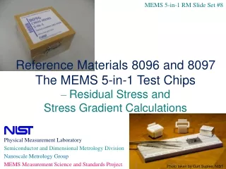
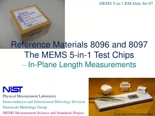
MEMS 5-in-1 RM Slide Set #11. Reference Materials 8096 and 8097 The MEMS 5-in-1 Test Chips – Remaining Details. Physical Measurement Laboratory Semiconductor and Dimensional Metrology Division Nanoscale Metrology Group MEMS Measurement Science and Standards Project.

E N D
MEMS 5-in-1 RM Slide Set #11 Reference Materials 8096 and 8097 The MEMS 5-in-1 Test Chips – Remaining Details Physical Measurement Laboratory Semiconductor and Dimensional Metrology Division Nanoscale Metrology Group MEMS Measurement Science and Standards Project Photo taken by Curt Suplee, NIST
Outline for the Remaining Details
1. Validation Procedures • Validation procedures are used to accept an instrument back into service • For height measurements • For frequency measurements • For length measurements
1a. Validation Procedure for Height Measurements • To accept instrument back into service: • Use two step height standards (SHS) • For example, a 1.0 µm and a 4.5 µm SHS • Calibrate the instrument using the 4.5 µm SHS • Careful – use only the certified region along both the length and width • Obtain cal4.5 • Six measurements are taken (3 along each side of the SHS) before the session (mean = ) • Six measurements are taken after the session (mean = ) • Obtain step height measurements on the 1.0 µm SHS • Obtain platNXa,platNXb,platNXc,platNYa,platNYb,platNYc • andsplatNXa, splatNXb, splatNXc, splatNYa, splatNYb, splatNYc • Calculate the calibrated step height measurement, M1.0, where • M1.0 = m1.0 cal4.5
1a. Validation Procedure for Height Measurements (continued) • Calculate uM1.0 • uM1.0=SQRT(uLstep1.02+uWstep1.02+ucert1.02+ucal1.02+urepeat(shs)1.02+udrift1.02+ulinear1.02+urepeat(samp)1.02) • where • uLstep1.0=SQRT{[((splatNXa+splatNXb+splatNXc)/3)calz4.5]2(sroughNXcalz4.5)2 • +[((splatNYa+splatNYb+splatNYc)/3)calz4.5]2(sroughNYcalz4.5)2} • uWstep1.0=STDEV(M1.0a, M1.0b, M1.0c ) • ucert1.0=(cert4.5/cert4.5)|M1.0| • ucal1.0=(6ave4.5 / )|M1.0| • urepeat(shs)1.0=(6same4.5 / )|M1.0| • udrift1.0=[zdrift4.5calz4.5/(2*SQRT(3)cert4.5)]|M1.0| • ulinear1.0=[zlin4.5/SQRT(3)]|M1.0| • urepeat(samp)1.0=(repeat(samp)1.0)|M1.0|
1a. Validation Procedure for Height Measurements (continued) • Determine D1.0 and uD1.0 D1.0=|M1.0-cert1.0| uD1.0=SQRT(uM1.02+scert1.02) • Repeat the above by switching the standards • Instrument accepted back into service if: • D1.0 < 2uD1.0 • D4.5 < 2uD4.5 • If above satisfied, can use either SHS, preferably the one closest in size to the step to be measured. • If above not satisfied, consider increasing zlin until the equations are in agreement.
1b. Validation Procedure for Frequency Measurements • To accept instrument back into service: • Use the round robin (RR) chip that was used for repeatability measurements (for C and M) • Obtain the certified value, C, and the expanded uncertainty, UC • C = the average YM value for the RR repeatability measurements • Obtain the measured value, M, and the expanded uncertainty, UM • M = the YM value using new measured frequencies and same inputs to Data Sheet YM.3 as for the RR • Obtain the difference, D, and the expanded uncertainty, UD • D = |C - M| • UD = SQRT[UC2 + UM2] • Ensure that D <UD 2. Or, compare the YM value obtained from 2 different instruments • Obtain the certified value, C, and the expanded uncertainty, UC • C = the YM value found from instrument #1 • Obtain the measured value, M, and the expanded uncertainty, UM • M = the YM value found from instrument #2 • Obtain the difference, D, and the expanded uncertainty, UD • D=|C-M| • UD= SQRT[UC2 + UM2] • Ensure that D <UD
1c. Validation Procedure for Length Measurements • Accept instrument back into service: • As specified for in-plane length calibrations • To compare measurements taken with 2 micrometers: • Compare measurements in the x- and y-directions for each combination of lenses • For micrometer #1, obtain R = rulerxand estimate R = xcal • Where rulerx is the maximum FOV in x-direction for the given combination of lenses • And xcal is the estimated standard deviation of this measurement • For micrometer #2, obtain M = rulerx and estimate M = xcal • Determine D • D = |M R| • CalculateuD • uD = SQRT(uM2+uR2) • where uM=Mand uR=R • The measurements are in agreement if, for each combination of lenses used for RM measurements in both the x- and y-directions, • D <2uD
2. Stability Test Results • Stability tests are used to monitor drifts in parametric values over time. • Measurements of residual strain taken quarterly for 2 years on RM monitors with different storage conditions. • N2-filled dry box • wooden box • clean plastic storage • For the stability plots that follow, • The parametric values are plotted with the UROI uncertainty bars.
2a. Stability Test Results(for RM 8096) • Storage for RM Monitors • N2-filled dry box • Clean plastic storage • Wooden box • Dirty plastic storage can introduce plasticizers • Plasticizers have the effect of increasing residual strain. • That RM moved to clean plastic storage. • Time “zeroed” when moved.
2b. Stability Test Results(for RM 8097 Lot 95, P2) • Storage for RM Monitors • N2-filled dry box • Clean plastic storage • Wooden box
Storage for RM Monitors • N2-filled dry box • Clean plastic storage • Wooden box 2c. Stability Test Results(for RM 8097 Lot 98, P2)
Summary of Stability Test Results • RM 8096 (for composite oxide) • For inert atmosphere • Residual strain appears constant over time • For plastic storage and wooden box • Residual strain increases over time • RM 8097 Lots 95 and 98 (for P2) • For different storage conditions • Residual strain appears constant over time
3. Homogeneity Plots • Homogeneity plots are used to determine whether or not the chips are acceptable candidates for use as RMs • Is the fabrication process sufficiently homogeneous?
3. Homogeneity PlotsInclude Expanded Uncertainties and Limits • Parametric value, PaveData sheet uncertainty, UDS Note: The 4 quantities above are specified on the Report of Investigation. For the homogeneity plots that follow: • The parametric values are plotted with the UROI uncertainty bars. • The average value is plotted on the right with the heterogeneity limits
4. What’s Next?(Decade to Decade) 2010-2019: Decade of Standard Reference Databases, Reference Materials, and Standard Reference Materials Supporting the documentary standards Decade of Roadmapping Roadmapping the future of MEMS and planning our role in that future 2000-2009: Decade of Standards: Leading the development of documentary standards for MEMS measurement methods (in ASTM and SEMI) • 1990-1999: Decade of Innovation and Patents: • Establishing credibility in MEMS research community via: • Innovative fabrication methods and devices and • Transferring MEMS fabrication technology and measurement methods to the MEMS community
4. What’s Next? Standard Reference Material (SRM)? Does industry want this? Reference Materials (RMs) CMOS MEMS 5-in-1 RM 8096 MEMS 5-in-1 RM 8097 Standard Reference Database (SRD 166) MEMS Calculator Web Pages validate industry measurements (http://srdata.nist.gov/gateway/) with the keyword “MEMS Calculator” Documentary Standards ASTM E 2244-11e1: In-plane length E 2245-11e1: Residual strain E 2246-11e1: Strain gradient SEMI MS2–1113: Step height MS4–1113: Young’s modulus Research & Development CMOS compatible MEMS Test structure and measurement method R & D Scientific publications
4. What’s Next?(What Would NIST Do?) • If there is a high demand for the RMs: • Consider making more • Pass off to an interested company for them to make more? • Develop a plan as to how to do this fairly (if more than 1 company) • Chip design – on-line • Materials used – provide them with the eDocs (which are public documents) which includes the list of vendors, etc.? • Calibration/measurement/analysis – in standards supplemented by the SP260 • DataSheets – on line for use • DataSheets (htm files) and figures – request from NIST (free of charge) or make available for download (also available with the purchase of an RM) • Draft DataSheets (htm files) with read and write capabilities for text files and figures – request from NIST (free of charge) or make downloadable • Miscellaneous (e.g., handling/storage/assembly of material/shipment/etc.) – in eDocs and SP260 • How would they report their values (like on ROIs)? Is an ROI associated exclusively with NIST? • How would their customers believe their values? Would they need to be accredited somehow?
4. What’s Next?(What Would NIST Do? - continued) • If there is a high demand for the RMs (continued): • Consider turning the RMs into SRMs • Via designing using SOI • Oxide and silicon layers may each be 70 nm • Can put next to linewidth structures • Can achieve a tighter control on the thickness measurements • Cantilevers/beams may require holes in them • Will the cantilevers and fixed-fixed beams bend enough? • Can reasonable images be obtained with the interferometer and vibrometer? • Look into this…..
5. Summary(Uses of the MEMS 5-in-1) Photo taken by Curt Suplee, NIST • To validate use of the documentary standards (so companies can compare their in-house measurements taken on the RM with NIST measurements) • To characterize or validate a process • To take local measurements • To compare measurements meaningfully (e.g., between suppliers and customers) • To trouble-shoot a process (to improve yield and track failure sources to speed development) • To calibrate an instrument Intended for • MEMS designers • Test equipment manufacturers • Who may want to buy in bulk to sell with their instruments • IC and MEMS foundries and services