Download
1 / 22
220 likes | 341 Views
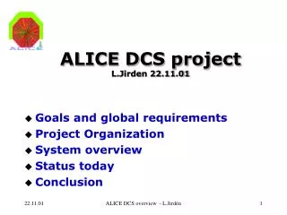
LHCC Comprehensive review ALICE DCS. 23 March 2004 L.Jirdén. Outline. Context Progress in 2003 Plans for 2004 Critical issues. 3. Services. ECS. 4. External Systems. power. cooling. gas. LHC. magnets. DAQ. Ctrl. infrastructure. Trigger. Ctrl. safety. HLT. Ctrl. access.

E N D
LHCC Comprehensive review ALICE DCS 23 March 2004 L.Jirdén
Outline • Context • Progress in 2003 • Plans for 2004 • Critical issues
3. Services ECS 4. ExternalSystems power cooling gas LHC magnets DAQ Ctrl infrastructure Trigger Ctrl safety HLT Ctrl access Controls Context 1. Back-end DCS ITS TPC MUON pixel strip drift T T p hv hv hv hv hv lv lv lv lv lv 2. Detectors
USER APPLICATION FRAMEWORK DBMS FSM ALARM ARCHIVAL CONDITION PVSS ARCHIVAL CONFIG PVSS CONFIG FEE CONFIG COMMUNICATION ACCESS DCS network 1. DCS Back-end
UIM UIM UIM DCS Ctrl API operator Full scale: ~ 25 PVSS systems on >100 computers A typical system has 40 000 parameters to control - each with alarm possibility PVSS scalability and Alarm handling are critical issues ! EVM DB DBM UIM UIM UIM UIM UIM UIM UIM UIM UIM … Dist Dist … Dist Dist Ctrl Ctrl Ctrl API API API … TPC TRD SSD EVM EVM EVM DB DB DB DBM DBM DBM … D D D D D D D D D DEVICE Distributed PVSS system
PVSS progress • New version released (December 03) • Better performance & robustness • Handling of distributed systems improved • Oracle archiving delayed to ‘August 04 release’ • Scalability • CERN tests: 130 PVSS systems on 15 computers • Static functionality ok; Dynamic behavior yet to be tested • LOFAR project test: 115 producer to 5 consumer PVSS systems • Scales well; ~700 ups/station measured • Alarm avalanches • 2 PVSS systems on 2 computers provoking 10000 alarms on each system • Result satisfactory
ALICE Back-end prototyping started Discussions started 1st version exists Redesigned USER APPLICATION Toolsprototyping started Improved FRAMEWORK DBMS FSM ALARM ARCHIVAL CONDITION PVSS ARCHIVAL CONFIG PVSS CONFIG FEE CONFIG COMMUNICATION ACCESS DCS network OPC, DIM protocols exist. prototyping DIP Prototyping started DB Prototyping started prototype tools ready 1. DCS Back-end
2. Detectors • Requirements • Detector URD’s have been completed to ~75% • Prototyping • All main detectors have started prototyping their sub-systems • ~10 prototypes implemented and working with PVSS • Common solutions • High Voltage & Low Voltage • Device drivers have been prototyped for most common devices • State machine behavior has been developed; being standardized • Front End Electronics • Generic device model (FED) has been defined and prototyped • A global configuration scheme has been defined and is being prototyped • General Purpose Monitor • A prototype solution has been developed • TPC, HMPID and SPD used as test case
ELMB PT1000 two wire sensors connected Can Bus port
supervisory applications process control applications ALICE CONTROL ROOM DCS LAN PLC Fieldbus Devices Sensors COUNTING ROOMS Devices Sensors CAVERN Devices Sensors ON DETECTOR 3. Services • Electricity • Rack control:prototyping has started • Rack monitor:PRR of main component done • Networks: Layout being defined • Cooling:basic design being finalized • Gas: prototype for TPC finalized • Magnets: 1st prototype installed & tested • Infrastructure: requirements being defined • Safety • Level 1 (DCS):interlocks & alarms being def. • Level 2 (DSS):implemented -being installed • Level 3 (CSAM): back-end operational, sensors being defined
Safety systems Fire brigadeto point 2 Cut group of racks Cut equipment gracefully DSS system Secure the zone Interlock spec. equipment Cut a single rack Safety actions DCS actions DSS alarm actions CERN Safety Alarm Monitoring (CSAM) DCS RedundantPLC’s DSS Emergency stop Fire/ smoke Emergency call Blocked lift Temp Cooling water Temp Power supplies I/O units Evacuation alarm Gas detection Water leak Power status Front-end electronics Cooling & gas Oxygen deficiency Flooding Detector status Infrastructure Dead-man device Experimentenvironment Level 3alarms Experimentequipment Hardwired interlock
4. Interface to TRG, DAQ, HLT via ECS • Basic communication scheme has been defined • Prototype for HMPID has been implemented and tested • Common Technical Design Report has been finalized
Plans for 2004 • Setting up a DCS lab • For development and test of • DCS infrastructure; powered racks, network (isolated), computers • ALICE DCS Back-end system • Common sub-system solutions • Available to detector DCS developers • For DCS reference systems • Systems to be installed • Test-beam support • TPC – May 04 • ITS – October 04
ECS DAQ TPC LV HV TMON FEE ANALOG DIGITAL ANODE GATING EDGE SKIRT TMON FEE WIENER PS WIENER PS ISEG PS ISEG PS ISEG PS ISEG PS TEMP sensors RCU DCS for TPC test-beam in May
Plans for 2004 • Pre-installation at surface of P2 • TPC – start Dec 04 • HMPID – start Dec 04
ECS DCS DAQ TPC LV HV TMON COOL FEE VHV RODC LASER PULSER GAS DU’s DU’s DU’s DU’s DU’s DU’s DU’s DU’s DU’s DU’s WIENER PS ISEG PS ELMB COOL PLANT RCU FUG ROD LASER SYSTEM PULSER SYSTEM GAS SYSTEM DCS for TPC pre-installation
2004 2003 2005 2006 2007 HW infrastructure Back-end + services Detector sub-systems Integration with DAQ/TRG/HLT Pre-installation on surface Final installation in UX M3 M1 M2 M4 HW infrastructure Back-end + services Detector sub-systems Integration with DAQ/TRG/HLT Commissioning Individual detectors Groups of detectors Whole experiment M5 M6 M7 M8 Schedule & Milestones
Critical issues • PVSS scalability • Dynamic behavior in full scale to be verified • B-field in UX • Find solutions for B-field sensitive components in the cavern • Cooling controls • 11 sizable PLC based systems to be provided by TS: • Design, planning and manpower to be verified
Conclusion • Visible progress in all fields of DCS • All basic back-end components are available today • Transition from requirements & design phase to prototyping & testing phase has taken place for all main detectors • Global planning and milestones respected by all main detectors
URD Status 1st draft URD exists Discussion started Not started or unknown PHO MU CAL CPV TRG TRA DCS ITS TPC TRD TOF HMP ZDC FMD T0 V0 PMD EMC ACC Detectors SPD SDD SSD HV HV HV HV VHV HV HV HV HV HV HV HV HV HV HV HV HV HV HV LV LV LV LV LV LV LV LV LV LV LV LV LV LV LV subsystems FEE FEE FEE FEE FEE FEE FEE FEE FEE FEE FEE FEE MON MON MON MON MON MON CCO MON MON MON MON MON MON MON CRT CRT CRT CRT CRT CRT CRT CRT CRT CRT CRT CRT CRT CRT CRT CRT COO COO COO COO TS COO COO COO COO COO COO COO GAS PLS GAS GAS GAS GAS GAS GAS GAS GAS GMS CAL ROD T0 LIQ LSR LSR GMS
Prototyping status 1st version implemented started not started but common solution exists Unknown or not started PHO MU CAL CPV TRG TRA DCS … ITS TPC TRD TOF HMP ZDC FMD T0 V0 PMD EMC ACC Detectors SPD SDD SSD HV HV HV HV VHV HV HV HV HV HV HV HV HV HV HV HV HV HV HV LV LV LV LV LV LV LV LV LV LV LV LV LV LV LV FEE FEE FEE FEE FEE FEE FEE FEE FEE FEE FEE subsystems MON MON MON MON MON MON MON MON MON MON MON MON MON MON CRT CRT CRT CRT CRT CRT CRT CRT CRT CRT CRT CRT CRT CRT CRT CRT COO COO COO COO COO COO COO COO COO COO COO GAS PLS GAS GAS GAS GAS GAS GAS GAS GAS GMS CAL ROD T0 LIQ LSR LSR GMS