Download
1 / 36
420 likes | 753 Views
Heat & Light (AP306) Part II: Optics. Dr.Haitao Huang ( 黄海涛 ) Department of Applied Physics, Hong Kong PolyU Tel: 27665694; Office: CD613 PowerPoint can be downloaded from http://ap.polyu.edu.hk/apahthua Textbook:

E N D
Heat & Light (AP306)Part II: Optics Dr.Haitao Huang (黄海涛) Department of Applied Physics, Hong Kong PolyU Tel: 27665694; Office: CD613 PowerPoint can be downloaded from http://ap.polyu.edu.hk/apahthua Textbook: Introduction to Optics, 2nd Edition, F.L.Pedrotti and L.S.Pedrotti (Prentice Hall 1993) Reference books: Optics, 4th Edition, E.Hecht (Addison Wesley Optics, 3rd Edition, A.Ghatah (McGraw Hill 2005) Waves—Berkeley Physics Course V.3, F.S.Crawford, Jr., (McGraw Hill 1968) Heat & Light----by Dr.H.Huang, Department of Applied Physics
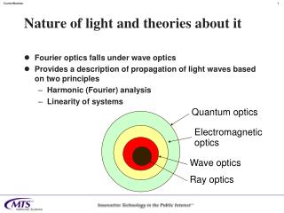
Nature of Light Duality in Nature: Rays of light can be regarded as streams of (very small) particles emitted from a source of light and traveling in straight lines. Light also takes a wave motion, spreading out from a light source in all directions and propagating through an all-pervasive medium. Light can be viewed as the electromagnetic radiation in a particular region of spectrum. Heat & Light----by Dr.H.Huang, Department of Applied Physics
Production and Measurement of Light Electromagnetic radiation may vary in wavelength (or frequency) and in intensity. Variation in wavelength is called electromagnetic spectrum. Variation in intensity is described by radiometry and photometry. Radiometry involves only physical measurement. Photometry involves the response of human eye. Radiant flux emitted per unit of solid angle by a point source in a specific direction is called the radiant intensity Ie (watts per sr=steradian), Irradiance Ee (watts per square meter) is the radiant flux received on a unit surface area, Radiance Le (watts per square meter per sr) is the radiant intensity per unit of projected area, perpendicular to the specific direction, Radiant intensity of a black body (or a perfectly diffuse scattering surface) follows the Lambert’s law, Heat & Light----by Dr.H.Huang, Department of Applied Physics
Production and Measurement of Light Visual Sensitivity: When we use photometric quantities, we are measuring the properties of visible radiation as they appear to the normal eye, rather than as they appear to an “unbiased” detector. The visual sensitivity varies with wavelength. The sensitivity curve, sometimes referred to as the luminosity curve of an equal energy spectrum, give the relative brightness, as assessed by the average eye, of the different colors of the spectrum when the incident energies at each wavelength have been reduced to the same mechanical value. For the average light adapted eye at moderate intensities (photopic vision) the maximum visual effect is obtained with light of wavelength 555nm (yellow-green). Heat & Light----by Dr.H.Huang, Department of Applied Physics
Production and Measurement of Light baffle Standard Source and Candela A standard must give a constant luminous output for an indefinite period of time. This restriction excludes all gas lamps, electric filament lamps, and discharge tubes from being used for standardization. The present primary standard source of light is based on the concept of a black body radiator. A black body is a device which absorbs entire radiation incident on it at all temperatures. When at a constant temperature a black body will be radiating the same energy that it receives, the total quantity depending on its temperature. Thus a black body is also a perfect emitter of radiation, and will emit more energy than any other body at the same temperature. The radiation from a black body is independent of the nature and material of the body. A hollow vessel with a blackened interior and single small hole provides the basis for a standard source. The unit of measurement of the luminous intensity of a source is candela. One candela is equal to one sixtieth (1/60) of the luminous intensity per square centimeter of a black body at the temperature of solidification of platinum. Heat & Light----by Dr.H.Huang, Department of Applied Physics
Production and Measurement of Light • Sources • Sunlight, skylight • Incandescent sources: blackbody; Nernst glower and globar; tungsten filament • Discharge lamps: monochromatic and spectral sources; high-intensity sources (carbon arc, compact short arc, flash and concentrated zirconium arc); fluorescent lamps • Semiconductor light-emitting diodes (LEDs) • Laser • Detectors • Thermal detectors: thermocouples and thermopiles; bolometers and thermistors; pyroelectric detector; pneumatic or golay • Quantum detectors: phototubes and photomultipliers; photoconductive; photovoltaic; photographic reflectance or reflection factor transmittance Heat & Light----by Dr.H.Huang, Department of Applied Physics
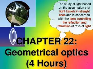
Geometrical Optics Law of Reflection When a ray of light is reflected at an interface dividing two uniform media, the reflected ray remains within the plane of incidence includes the incident ray and the normal to the point of incidence. Law of Refraction (Snell’s Law) When a ray of light is refracted at an interface dividing two uniform media, the transmitted ray remains within the plane of incidence and the sine of the angle of refraction is directly proportional to the sine of the angle of incidence. Heat & Light----by Dr.H.Huang, Department of Applied Physics
Geometrical Optics Huygens’ Principle Wavefront: the locus of the points which are in the same phase. For example, if we drop a small stone in a calm pool of water, circular ripples spread out from the point of impact, each point on the circumference of the circle (whose center is at the point of impact) oscillates with the same amplitude and same phase and thus we have a circular wavefront. Each point of a wavefront is a source of secondary disturbance and the wavelets emanating from these points spread out in all directions with the speed of the wave. The envelope of these wavelets gives the shape of the new wavefront. Heat & Light----by Dr.H.Huang, Department of Applied Physics
Geometrical Optics Heat & Light----by Dr.H.Huang, Department of Applied Physics
Geometrical Optics Fermat’s Principle The Fermat’s Principle is also called the “principle of least time”. The field of geometrical optics can be studied by using Fermat’s principle which determines the path of the rays. The ray will correspond to that path for which the time taken is an extreme in comparison to nearby paths, i.e., it is either a minimum or a maximum or stationary. The mathematical form of the Fermat’s principle is, where n is the refractive index and the integration is done along the path. Heat & Light----by Dr.H.Huang, Department of Applied Physics
Geometrical Optics Principle of Reversibility: Any actual ray of light in an optical system, if reversed in direction, will retrace the same path backward. This principle is directly derived from the Fermat’s principle. Reflection in Plane Mirrors Specular reflection: the reflection from a perfectly smooth surface which obeys the law of reflection. A virtual image of a point object S is formed at point S since the rays of light appear to come from that point. SA=SA The image is the same size as the object. The image is reversed, laterally inverted and upright. Specular reflection from the xy-plane: the reflected ray PQ remains within the plane of incidence, making equal angles with the normal at P. If the direction of the incident ray is described by its unit vector, r1=(x, y, z), then the reflected ray is r2=(x, y, z) Heat & Light----by Dr.H.Huang, Department of Applied Physics
Geometrical Optics Refraction through Plane Surfaces: For rays making a small angle with the normal to the surface, a reasonably good image can be located. In this approximation, we only allow paraxial rays to form the image. Since n1>n2, the virtual image S of the point object appears to be nearer than it actually is. A critical angle of incidence C is reached when the angle of refraction reaches 90°. For angles of incidence larger than this critical angle, the incident ray experiences total internal reflection, as shown. Heat & Light----by Dr.H.Huang, Department of Applied Physics
Geometrical Optics Imaging by an Optical System An optical system includes any number of reflecting and/or refracting surfaces, of any curvature, that may alter the direction of rays leaving an object. The region may include any number of intervening media, but we assume each individual medium is homogenous and isotropic, and so characterized by its own refractive index. The rays from the object point O spread out radially in all directions in real object space. In real object space the rays are diverging and spherical wavefronts are expanding. Suppose that the optical system redirects these rays in to the real image space, the wavefronts are contracting and the rays are converging to a common image point I. From Fermat’s principle, the rays are said to be isochronous. Further, by the principle of reversibility, if I is the object point, the image point will be O. The points O and I are said to be conjugate points for the optical system. Both points O and I can be imaginary. Reflecting or refracting surfaces that form perfect images are called Cartesian surfaces. Heat & Light----by Dr.H.Huang, Department of Applied Physics
Geometrical Optics Spherical Surface: Spherical mirrors may be either concave or convex relative to an object point O, depending on weather the center of curvature C is on the same or opposite side of the surface. Heat & Light----by Dr.H.Huang, Department of Applied Physics
Geometrical Optics Reflection at a Spherical Surface: One ray originating at O is normal to the spherical surface at its vertex V and the other is incident arbitrary at P. The intersection of the two rays (extended backward) determines the image point I conjugate to O. The image is virtual, located behind the mirror surface. Similarly, for a concave mirror, we can have • The object distance s is positive when O is a real object. When O is a virtual object, s is negative. • The image distance s is positive when I is a real image, and negative when I is a virtual image. • The radius of curvature R is positive when C is to the right of V, corresponding to a convex mirror, and negative when C is to the left of V, corresponding to a concave mirror. Heat & Light----by Dr.H.Huang, Department of Applied Physics
Geometrical Optics Focal Length: For an object at infinity, the image distance is the focal length, The focal length is positive for a concave mirror and negative for a convex mirror. The mirror equation can be written as, Lateral magnification: We assign a (+) magnification to the case where the image has the same orientation as the object and a () magnification when the image is inverted relative to the object. Heat & Light----by Dr.H.Huang, Department of Applied Physics
Geometrical Optics • Graphic diagram for spherical mirrors: • parallel to the principal axis are reflected though F; • passing through F are reflected parallel to the principal axis; • passing through C is reflected back along the same path. Heat & Light----by Dr.H.Huang, Department of Applied Physics
Geometrical Optics Example:An object 3 cm high is placed 20 cm from (a) a convex and (b) a concave spherical mirror, each of 10 cm focal length. Determine the position and nature of the image in each case. Solution:(a) Convex mirror: f=-10 cm and s=+20 cm. From mirror equation, we get s=-6.67 cm The image is virtual, 6.67 cm to the right of the mirror vertex, and is erect and 1 cm high. (b): Concave mirror: f=+10 cm and s=+20 cm. From mirror equation we obtain s=20 cm and, therefore, m=1 The image is real, 20 cm to the left of the mirror vertex, and is inverted and the same size as the object. Heat & Light----by Dr.H.Huang, Department of Applied Physics
Geometrical Optics Refraction at a Spherical Surface: Employing the same sign convention for mirrors, Lateral magnification: Heat & Light----by Dr.H.Huang, Department of Applied Physics
Geometrical Optics Example:A real object is positioned in air, 30 cm from a convex spherical surface of radius 5 cm. To the right of the interface, the refractive index is 1.33. What is the image distance and lateral magnification of the image? Solution:s=30 cm and R=5 cm. This gives cm which means the image is real. indicating an inverted image. As shown in the figure, suppose now the second medium is only 10 cm thick, forming a thick lens, with a second, concave spherical surface, also of radius 5 cm. The refraction by the first surface will be unaffected by this change. Inside the lens, before a real image is formed, rays are intercepted and again refracted by the second surface to produce a different image. We have s2=30 cm and R2=5 cm. So, s2=9 cm. It is a real image. Heat & Light----by Dr.H.Huang, Department of Applied Physics
Geometrical Optics Thin Lenses: Two spherical surfaces are involved in a thin lens. 1st refracting surface of radius R1, 2nd surface of radius R2, For thin lens, lensmaker’s equation: Lateral magnification: A (convex) lens is thicker in the middle: positive focal length. A (concave) lens thinner in the middle: negative focal length. Thin lens equation: Heat & Light----by Dr.H.Huang, Department of Applied Physics
Geometrical Optics Ray Diagram for Thin Lenses: Thin lenses are best represented, for purpose of ray construction, by a vertical line with edges suggesting the general shape of the lens. Heat & Light----by Dr.H.Huang, Department of Applied Physics
Geometrical Optics Example:Find and describe the intermediate and final images produced by a two-lens system such as the one sketched in Fig.3.16(a). Let f1=15 cm, f2=15 cm, and their separation be 60 cm. Let the object be 25 cm from the first lens. Solution: For the first lens, s1=25 cm. cm Thus the first image is real and inverted. For the second lens we have s2=6037.5=22.5 cm. Then, cm Thus the final image is virtual and inverted. The overall magnification is m=m1m2=0.6. Heat & Light----by Dr.H.Huang, Department of Applied Physics
Geometrical Optics Vergence and Refractive Power: The reciprocal of distance is defined as vergence, which represents the curvature of wavefront incident or emerge from a lens. They are, The change in curvature from object space to image space is due to the refracting power P of the lens, given by 1/f. With these definitions, the thin lens equation can be written as, When the lengths are measured in meters, the powers have units of diopters (D). The refractive power of a surface is (n2n1)/R. When several thin-lenses are placed together, the overall refractive power is the sum of the individual refractive powers, Heat & Light----by Dr.H.Huang, Department of Applied Physics
Geometrical Optics Newtonian Equation for the Thin Lens Heat & Light----by Dr.H.Huang, Department of Applied Physics
Matrix Methods in Paraxial Optics • Thick Lens: • Thick lens is a lens whose thickness along its optical axis cannot be ignored without leading to serious errors in analysis. • Six Cardinal points: • first and second system focal points (F1 and F2); • first and second principal points (H1 and H2); • first and second nodal points (N1 and N2). • Planes normal to the axis at these points are called cardinal planes. Heat & Light----by Dr.H.Huang, Department of Applied Physics
Matrix Methods in Paraxial Optics Basic Equations: Distances are directed, positive or negative by a sign convention that makes distances directed to the left negative and distances to the right, positive. Heat & Light----by Dr.H.Huang, Department of Applied Physics
Matrix Methods in Paraxial Optics Example:Determine the focal lengths and the principal points for a 4-cm thick, biconvex lens with refractive index of 1.52 and radii of curvature of 25 cm, when the lens caps the end of a long cylinder filled with water (n=1.33). Solution:nL=1.52, n=1, n=1.33, t=4 cm, The first refraction surface is a convex plane, so R1=25cm. The second one is a concave plane, so R2=25cm. According to equation we can get f1=35.74cm to the left of the first principal plane. From we have f2=47.53cm to the right of the second principal plane. Equations give us r=0.715cm and s=2.60cm. Heat & Light----by Dr.H.Huang, Department of Applied Physics
Matrix Methods in Paraxial Optics Matrix Method: In the paraxial approximation, changes in height and direction of a ray can be expressed by a linear matrix equation that links the image and object rays. The matrix is characteristic of an optical system. Translation Matrix: The 22 ray-transfer matrix represents the effect of translation on the ray. Heat & Light----by Dr.H.Huang, Department of Applied Physics
Matrix Methods in Paraxial Optics Refraction Matrix: The refraction of a ray is illustrated in the figure. We need to add a sign convention for the angles: angles are considered positive for all rays pointing upward, either before or after a reflection; angles for rays pointing downward are considered negative. (y,) and (y,) can be related by the followings, Heat & Light----by Dr.H.Huang, Department of Applied Physics
Matrix Methods in Paraxial Optics Reflection Matrix: Consider the reflection at a spherical surface as shown. We have, y=y, and Heat & Light----by Dr.H.Huang, Department of Applied Physics
Matrix Methods in Paraxial Optics Thick-Lens and Thin-Lens Matrices: In traversing the thick lens, the ray undergoes two refractions and one translation. For the first refraction For the translation For the second refraction Finally The entire lens For thin lens Heat & Light----by Dr.H.Huang, Department of Applied Physics
Matrix Methods in Paraxial Optics System Ray-Transfer Matrix: For an optical system which includes any number N of translations, reflections, and refractions, the following general relation exists. The ray transfer matrix (or system matrix) is The determinant of the system matrix has a very useful property: where n0 and nf are the refractive indices of the initial and final media of the optical system. Heat & Light----by Dr.H.Huang, Department of Applied Physics
Matrix Methods in Paraxial Optics Example: Find the system matrix for the thick lens. R1=45cm, R2=30cm, t=5cm, nL=1.60, and n=n=1. Solution: Using system matrix, We get Heat & Light----by Dr.H.Huang, Department of Applied Physics
Matrix Methods in Paraxial Optics Significance of System Matrix Elements: D=0 A=0 B=0 C=0 Heat & Light----by Dr.H.Huang, Department of Applied Physics
Heat & Light----by Dr.H.Huang, Department of Applied Physics