Download
1 / 17
190 likes | 522 Views
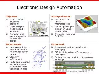
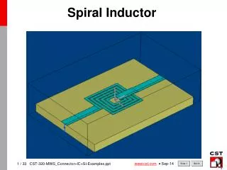
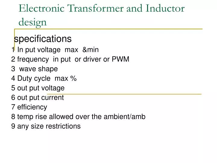
Electronic Transformer and Inductor design. specifications 1 In put voltage max &min 2 frequency in put or driver or PWM 3 wave shape 4 Duty cycle max % 5 out put voltage 6 out put current 7 efficiency 8 temp rise allowed over the ambient/amb 9 any size restrictions.

E N D
Electronic Transformer and Inductor design specifications 1 In put voltage max &min 2 frequency in put or driver or PWM 3 wave shape 4 Duty cycle max % 5 out put voltage 6 out put current 7 efficiency 8 temp rise allowed over the ambient/amb 9 any size restrictions
Design considerations • core materials- freq/temp/shape/efficiency • conductor material- freq /current/reg • Insulation-temp class/voltage • Core shape/size-power /temp/EMI • Winding type –leakage/isolation
Design assumptions • VA ratings or wattage and duty • Flux density • Current density • Window utilization • Insulation/temp allowed for hot spot • Efficiency -Iron losses Copper losses
Design equations • 1 Ap=window area x core cross section (cm**4) =(2va*10**4/kf*kj*ku*Bm*f)**1.14 • Kf = form factor 4.44 for sine 4 for square wave • Kj=temp rise factor 535 for 50C rise • Ku= window utilization factor 0.4 • Bm =flux density max • f = frequency • 2. E=Kf*Bm*Ac*N*f • E=volts& N=turns. Vin =input volts, Vout=out put N1=pri turns N2= sec turns .Ton/T=duty cycle • 3. out put volts(Vout)=Vin)*N2/N1xTon/T
Winding of coils • Primary -layer /sectional • Sec – layer/sectional • Inter layer insulation • Inter winding insulation • Shields • Sand witch winding • Bifilar winding
Core assembly &properties/types • EI or UI or EE-inter leaving/but joint/weld • Air gap/ shunt leakage • No load losses/magnetizing current • Eddy current/hysteresis losses • Saturation • Polarisation • Toroidal/rectangular R core, • Cut core
Clamping &binding • Mechanical clamps, • Binding with adhesive tapes • Encapsulation& varnishing/finishing • Magnetic shield and covers • Mounting arrangements
Terminations wires tinning /sleeving insulation Lugs fitting, crimping & tinning barrier blocks /studs/eye/ lets terminal boards/connectors/ pins / spades
Testing • Testing for inductance, resistance leakage inductance • Breakdown and insulation • In case of mains freq at in put rated volt • Open circuit test • Magnetising current & losses out put voltages • Short circuit test= rated sec current passed with sec(out put) shorted with adjusted low volts to pri(in put) • on load voltages = out put voltage with rated in put voltage applied to in put out put loaded with rated currents • Temp rise test
Inductors specification • Inductance value (mH) • Frequency • Dc current • Ac current / ripple content • Working voltage • Temp rise/ ambient of working/class of ins
Design consideration • Core – freq & power LI**2 • Conductor - freq & rms current/density • Insulation-class/ temp rise/voltages • Size restrictions • EMI considerations
Design Equations • 1 Area Product Ap=(LI**2*10**4/BmKuKj)**1.14=Wa*Ac • L=inductance in henries; I=current peak in amp • Bm=flux density in Tesla depending on the material, losses l&freq; ku=utilisationfactor(0.4);Kj=temp rise factor(535 for 50C); • Wa=window area; Ac=core cross section in cm**2 • 2. Turns N=LI*10**4/BmAc • 3 air gap g=1.26*N**2Ac/L10**7
Construction • Winding • Assembly of core • Adjustment of air gap • Clamping and finishing • termination
Other considerations • Inductors design with DC currents create polarization resulting poor Mu values and to avoid saturation we need to introduce air gaps.But these gaps will have fringing flux giving rise to proximity effect and EMI • With current the value L tend to swing to lower hence customary to adjust L +10 to20% unless used for tuning. • Inductors for ripple filters in power supply need to respond dc current and low freq ripple; in case • 1ph 3 ph full wave 2*f ) 6*f Half wave f 3*f
Testing • Inductance • Resistance • Leakage inductance • Hi-pot • DC bias • AC Voltage and current (at low freq if app)
Electronic transformers have to be tested indirectly by inductance and leakage inductances in the absence of functional zigs or power sources. Core manufacturer gives 25% tolerances hence the inductance also have similar tolerance. Small air gap can give us less variation for core variation& temp variation Since power density Watts/vol or area is high in power electronic supplies the forced air cooling is recommended for higher than 500W Inductors also have to be tested indirectly other than mains freq where z=v/I&L=z/3.14*2f conclusion