Download
1 / 39
470 likes | 779 Views
Integral Field Spectroscopy. Jeremy Allington-Smith University of Durham. Contents. Advantages of Integral Field Spectroscopy Datacube "theorem" Techniques of IFS Lenslet-array Fibres+lenslets Image-slicing Multiple IFS. What is IFS?.

E N D
Integral Field Spectroscopy Jeremy Allington-Smith University of Durham
Contents • Advantages of Integral Field Spectroscopy • Datacube "theorem" • Techniques of IFS • Lenslet-array • Fibres+lenslets • Image-slicing • Multiple IFS
What is IFS? • Integral field spectroscopy produces a spectrum of each part of an image simultaneously • This results in a datacube with axes (x, y,l) • This is sometimes called "3D imaging" or "2D spectroscopy" or even "3D spectroscopy"! • 3D techniques which also produce a datacube but not from a single observation (e.g Fabry-Perot or FTS) are not usually called IFS
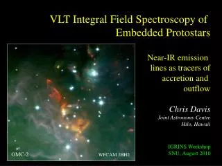
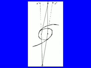
Why use IFS? Direct image Radial velocity Close up "Boring" elliptical galaxy with odd kinematics! SAURON: NGC 4365 (Lyon/Durham/Leiden/ESO)
Where do you put the slit? • Slit gives only a 1D slice through object • Slit captures only part of the object's light • Only a 3D technique reveals the global velocity field
Generic advantage of IFS IFS – use info from adjacent slices to correct velocity data Slit spectroscopy – velocities in error since blobs not centred in slit dispersion • Spectroscopy over full 2D field with high filling factor • No slit losses - all the light is used • Point and shoottarget acquisition reduces operational overheads • Can reconstruct white-light imageto aid interpretation (and target acquisition) • Almost immune to atmospheric dispersion • More accurate radial velocity determination: • Obtain global velocity field - not just a 1-D section • Velocity field can be reconstructed accurately without errors due to position of features within slit
Applications • Galaxy kinematics: stars and gas (em & abs lines) • Distribution of ionising radiation (line ratios) • Distribution of stellar populations (lines/continuum) • Studies of interacting galaxies (kinematic resolution) • Unbiassed searches for primaeval line-emitting galaxies (may be invisible in broadband image) • Searches for damped Lya aborbers near line of sight to QSOs (with large impact parameter) • Outflows from young stellar objects
Dissecting active galaxies Velocity field (narrow Pab) Distribution of [FeII] NGC4151 observed with SMIRFS-IFU in J-band - Turner et al. MNRAS 331, 284 (2002)
Datacube "theorem" Datacube with same equivalent volume Nnm y l x To first order… all 3D methods are equally efficient in generating the same datacube volume with the same number of pixels N observations each with n x m pixels Spectral and spatial information encoded on detector in any way you like
Imaging spectroscopyE.g. Fabry-Perot interferometry & narrow-band imaging y l x Each slice contains the full field imaged in one passband Devote pixels entirely to imaging: Datacube sliced into thin slices in wavelength. Repeat observations with different wavelength range Sensitive to changes in sky background
Longslit spectroscopy y l x Each slice is one longslit spectrum Longslit spectroscopy: Each longslit pointing produces a xl slice Full datacube produced by stepping longslit in y NB: No spatial information in y within each slice
Integral field spectroscopy y l x Each piece contains all the spectra within a narrow field Devote pixels mostly to spectroscopy: datacube sliced into narrow spatial fields - repeat observation with different pointings
... to second order? • Which technique wins depends mostly on: • the dominant noise source • detector read noise • detector dark current • photon noise from sky • photon noise from object • temporal variability in sky background • how many pixels you can afford • details of the scientifc application, especially: • the size of the total field required • the length of the total spectrum required • A tradeoff between FTS and IFS for NGST/IFMOS indicated that IFS was preferrable
IFS "efficiency" Aim is to maximise a figure of merit that is a function of: # spatial samples , # spectral samples ,throughput # spatial samples:pack spectra together tightly along slit. Overlaps will result between samples at the slit but this is okay if: • there is Nyquist sampling of the field at the IFU input • adjacent spectra come from adjacent elements on the sky • there is no wavelength offset between adjacent spectra # spectral samples:maximise length of spectrum to fill complete detector length but, for a given detector, (#spatial #spectral) constant so can have multiple slits to increase #spatial by reducing #spectral throughput:efficient design Make the best possible use of the available detector pixels by minimising the dead space between spectra
Techniques of IFS Like SAURON and OASIS. Overlaps must be avoided low information density in datacube Telescope focus Spectrograph input Spectrograph output Pupil imagery Lenslets Datacube slit y Fibres+ lenslets Fibres x 1 Image slicer slit Mirrors 2 Only the image slicer retains spatial information within each slice/sample high information density in datacube 3 4 1 2 3 4 Both designs maximise the spectrum length and allows more efficient utilisation of detector surface.
Lenslet IFU • Example: SAURON* designed for wide-field galaxy kinematics • Short wavelength range for low-redshift MgB (517.4nm) • Spectra must not overlap otherwise information lost Sauron built by CRAL (Lyon) *Bacon et al. MNRAS 326, 23-35 (2001)
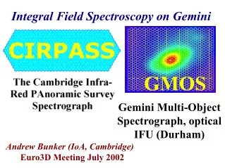
Lenslet+fibres: optical principle Microlens array Enlarger Pickoff Slit (out of page) mirror Telescope focus sky pupil Fibre bundle image image fibre fibre grating slit Spectrograph GMOS-IFU Allington-Smith et al PASP 114, 892 (2002)
Fibre+lenslet detection process Original image x Input y x y Pseudo-slit x y Overlaps here don't matter Computer Detector x y’ y monochromatic image of pseudo-slit y reconstructed monochromatic image of sky x x Ensure critical sampling here! Allington-Smith & Content, PASP 110,1216 (1999)
GMOS-IFU Integral Field Unit Gemini instrument support structure fore optic support structure on-instrument wavefront sensor collimator filter wheels IFU/mask cassettes GMOS without enclosure and electronics cabinets grating turret & indexer unit Dewar CCD unit main optical support structure shutter camera GMOS • 0.07 arcsec/pixel image scale • 5.5 x 5.5 arcmin field • 0.4 - 1.1mm wavelength coverage • R = 10,000 with 0.25” slits • Multiobject mode using slit masks • Integral fieldspectroscopy mode • Active control of flexure
The IFU Location of slits (covered) Slit mask (containing two pseudoslits) interfaces with GMOS mask changer
Exploit good images from GEMINI 0.2" sampling Unit filling factor Fibres coupled to close-packed lenslet array at input Largest possible object field 7" x 5" (1000 fibres) Provision to optimise accuracy of background subtraction extra 5" x 3.5" field offset by 60" from object field for background estimation (500 fibres) Transparent change between modes IFU deployed by mask exchanger, input & output focus coplanar with masks High efficiency lenslet-coupled at output and input to convert F/16 beam to ~F/5 for efficient use with fibres Use of low risk construction technique (GEMINI request to reduce risk to schedule) fibre+lenslet not image slicer Requirements & solutions
Field to slit mapping 1 slit block containing 2 rows 6144 pixels 1 arcmin Optionally block off this slit to double spectrum length but halve field 4608 pixels
Field to slit mapping 6144 pixels • One slit blocked to give • Longer spectra • Half the field (can still beam-switch) 4608 pixels
Background subtraction Position of reference star during beam-switch Position of reference star during beam-switch Typical/generous isoplanatic patch Typical/generous isoplanatic patch Object field Background field 5.5' 1 arcmin Field for Adaptive Optics • Various subtraction strategies • Beam switching supported • Optimised for AO (Altair in I)
GMOS integral field unit observes NGC1068 The IFU records a spectrum for each element Image taken by GMOS without using the IFU One spectrum for each element (only 4% shown) One image at each velocity form the datacube (only 4% shown)
NGC1068 - raw data Red Blue [OIII] Individual fibre spectra
Composite plot of representative [OIII]4959+5007 spectra over the field The velocity structure is very complex. NGC1068 - spectra
NGC1068 - datacube Bowshock NE Jet Observer Galaxy disk Nucleus SW NE • 8 x 10" field (mosaiced from 5 pointings) • Scan through [OIII]5007 line SW Miller, Allington-Smith, Turner, Jorgensen
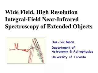
Developed from MPE's 3D by the University of Durham for highly-efficient spectroscopy over a two-dimensional field Optimum use of detector pixels since complete slices of sky are imaged (no dead space between spatial samples) Correct spectral sampling is obtained without degrading spatial resolution in dispersion direction Diffraction is only a 1-D issue reduction in optics size/mass Optics may be diamond-turned from the same material as the mount to reduce thermal mismatch good for space/cryo applications Adopted by GEMINI 8m Telescopes Project (GNIRS-IFU) and proposed by ESA for NGST Advanced ImageSlicer (AIS) To spectrograph Field optics (slit mirrors S3) Spectrogram Pseudo-slit Slicing mirror (S1) Field before slicing Pupil mirrors (S2) From telescope and fore-optics Focal plane
Gemini Near-IR Spectrograph (0.2 x 0.1 x 0.1)m3 and 1Kg • Cryogenic 1-5m spectrograph for GEMINI with IFU deployable via slit slide • GNIRS - NOAO, GNIRS-IFU - University of Durham
GNIRS-IFU summary • Wavelength range: • Optimal: 1.0-2.5 m • Total: 1.0-5.0 m • Field: 3.2”x 4.4” • Sampling: 0.15” • Spatial elements: 625 • Spectrum length: 1024 px • Cryogenic environment • IFU fits in module in GNIRS slit slide
Optical layout Slice 1 Slice 2 From GNIRS fore-optics F2, 1st reimaging mirror F1, pickoff mirror S3, slit mirrors S2, pupil mirrors F3, 2nd reimaging mirror S1, Slicing mirror To GNIRS collimator
Optical layout Bi-lithic S1 showing split Monolithic S2 MonolithicS3 F2 S1
MOS with IFS? - NGST/IFMOS Field 46x40" Sampling 0.19x0.19" Field 3.8x2.6" Sampling 0.05x0.05" Fore-optics Fore-optics Fore-optics Fore-optics Fore-optics Fore-optics Fore-optics Slicing unit Slicing unit Slicing unit Slicing unit Slicing unit Slicing unit Slicing unit Spectrograph (1 slit) Blue+Red spectrograph (9 slits) Blue+Red spectrograph (9 slits) Blue+Red spectrograph (9 slits) 4k x 4k detector 1 slit 2kx2k detector 9 slits LR HR Work by NGST-IFMOS consortium sponsored by ESA
Did IFMOS get on NGST? No, but small-field IFU may be included in NIRSPEC alongside MOS mode Work by NGST-IFMOS consortium sponsored by ESA. Picture from Astrium
Multiple IFS • IFS of multiple targets over wide field via deployable IFUs MOS with mapping to e.g. measure mass of many galaxies • Total number of elements set by number of detector pixels: • This must be divided amongst the different IFUs • For example, 20 modules with 200 elements each could be accommodated on a 4k x 4k detector small field/module • Main focus is on near-infrared • Exploit "wide-field" AO on GEMINI and VLT • Existing small-field IFU system: VLT/Flames (NB: Falcon) • Prototyping underway for image-slicing (e.g. VLT/KMOS)
Large-field multi-IFU prototype Output (slit for test only) Input 30' prime focus field Probe arm + optics Individual field 15 x 15 (4.5" x 4.5") • Complete deployable IFU module of 225 elements (Subaru F/2) • Fishing rod deployment Deqing Ren, PhD thesis, 2001. University of Durham
GIRMOS: gnomes around a pond The enclosing circle is 530mm diameter for a 93mm diameter field-of-view Feeds fixed image-slicing IFUs UK-ATC
GIRMOS pickoff arm light path From fore-optics To fixed image slicer IFU • stepping motor drive via worm gears • for both ‘shoulder’ and ‘elbow’ actions • two tubular arms in CFRP • the arms are not co-planar • four folds in each optical path • light re-imaged at x1.5 magnification UK-ATC