Download
1 / 33
370 likes | 588 Views
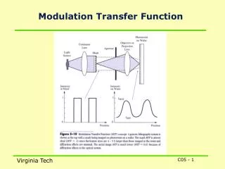
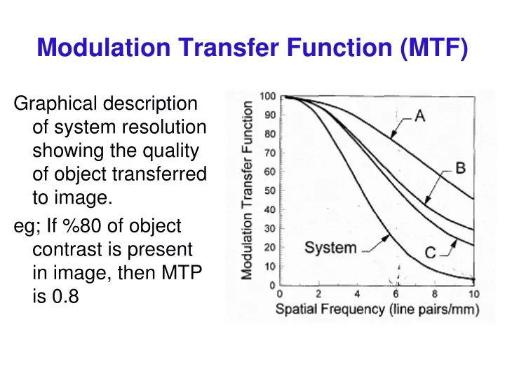
Modulation Transfer Function (MTF). Graphical description of system resolution showing the quality of object transferred to image. eg; If %80 of object contrast is present in image, then MTP is 0.8.

E N D
Modulation Transfer Function (MTF) Graphical description of system resolution showing the quality of object transferred to image. eg; If %80 of object contrast is present in image, then MTP is 0.8
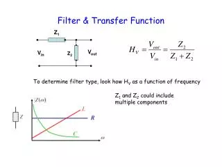
If object size (eg; The thickness of slit in a lead plate or Line in LSF) is , then spatial frequency is:Spatial Frequency =1/(2)
Frequency and space (time) are convertible to each other. Therefore, taking Fourier Transform of LSF we get MTF. h(x,y)=LSF
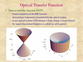
An object can be represented by its frequency components (Sinusoidal signals) using FT. • Then comparing these information with the MTF of system, we can evaluate the system to see if it can transfer the essential details (eg; Whether it can reconstruct the degraded information lost by Sampling) • FT of Noise is also useful to evaluate the system for transferring or eliminating noise information through the system. • FT of noise (Power spectrum or Wiener spectrum) is compared with the MTF of the system.
MTF measurement • A sinusoidal test phantom (a series of slits or square shape holes) is fixed in distance F from Source and d from Film. M=(F+d)/F Then, the image of slits at various size are obtained.
MTF measurement • Modulation (Contrast) of object is obtained for a point source as M’ • Where: • To = density changes • Tav = Average density on film • To+ = Maximum density • To- = Minimum density
MTF measurement • Modulation (Contrast) of image is obtained using the actual Focal Spot M • H(f) is less than 1, and It can be shown that H(f) is equivalent to FT of Focal Spot (PSF) with an addition of Magnification factor M. • Therefore for calculation of MTF, first FT of Focal Spot should be obtained, then its Frequency is modified (decreased) by M.
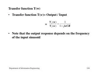
Experimental measurement of MTF • Input Modulation is: A = Amplitude • Output Modulation is: Usualy Output Modulation is smaller than Input Modulation Since the Modulation of both Input and Output are similar at frequency of 0, therefore MTF is 1 in zero frequency. In addition the MTF of Input is close to 1 at all frequencies. therefore, MTF of Output can be normalized and written as:
TungstenTarget Electrons (+) (--) Cu cathode Titling angle q Sin20° = 0.342, Sin16.5 =0.284 Apparent focal spot size X-Rays
17 MTF of various shape of Focal Spot
Focal Spots MTF depend on the shape and size of focal spot and magnification of image.For example; MTF of Square or Double pick focal spot is: M=Magnification m = M –1 a0 = focal spot width f = frequency of signal
Pinhole Source z Detector plane d
Finite source The total detected Intensity (image) of a transparent object (hole) having transmission t(x,y) = exp [ -µ (x,y) (z - zo)]imaged by a finite x-ray source, s(x,y) is obtained by convolution process: The detected image will be the convolution of a Magnified object and a magnified source. In frequency domain:
Square wave test patterna) in contact with Filmb) in contact with Screenc) same distance from filmMTF of Film MTF of Screen MTF of Target
Aliasing Oversampliny of LSF


![1. X resolution[95] AROC Curve BModulation Transfer Function CH D Curve DContrast-Detail Curve](https://cdn4.slideserve.com/1390808/slide1-dt.jpg)