Download
1 / 19
190 likes | 194 Views
Mechanics of Materials E NGR 350 - Lecture 22 Torsion 1. I am strong because I’ve overcome weakness I am fearless because I’ve overcome fear I have a twisted sense of humor because I’ve overcome torsion -Dr. Dan. Torsion and torque. Torsion - a state of being twisted

E N D
Mechanics of Materials ENGR350 - Lecture 22 Torsion 1 I am strong because I’ve overcome weakness I am fearless because I’ve overcome fear I have a twisted sense of humor because I’ve overcome torsion -Dr. Dan
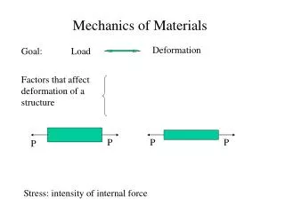
Torsion and torque • Torsion - a state of being twisted • Torque - a moment that tends to twist a member about it’s longitudinal axis • A shaft is the simplest member that transmits a torque • What are other things that experience torsion?
Torsion and Assumptions • For solid and hollow circularcross-sections we make the following assumptions: • Cross-sectional planes remain planar • Radial lines on these planes remain straight • Cross-sections rotate about the longitudinal axis, and remain perpendicular to that axis • No axial strain present due to torsion These assumptions are not valid for anything other than a shaft with a circular cross-section! (solid or hollow)
Torsional Shear Strain Pure torsionAll portions of the shaft are subjected to the same torque • Side angle γ, - Constant throughout length of member • Angle of twist 𝜙 - varies throughout length of member γ 𝜙 γ 𝜙1 γ 𝜙2
Developing the Shear Strain Equation Consider a small disk-shaped section of the shaft c – distance to from centerline to outside of shaft (shaft radius) Δx– small segment of shaft length ρ – radial distance from centerline Δϕ – change in twist over Δx
Developing the Shear Strain Equation Consider a small disk-shaped section of the shaft Defining γ: But can express D’D’’ using arc length
Developing the Shear Strain Equation Consider a small disk-shaped section of the shaft Small Angle Approximation: Or, written as: Eqn. 6.1
Developing the shear strain equation Consider a small disk-shaped section of the shaft Max shear strain when ρ = c Since linear, can express strain at a given distance from centerline as a ratio of the maximum shear strain: Eqn. 6.2 Eqn. 6.3
Torsional Shear Stress • Recall Hooke’s law for shear • Substitute this in to Eqn 6.3 to get: • Shear stress is linear across the radius. • It is zero in the center • It is maximum at the outside • Not just on the surface, but as Eqn. 6.4
Relating Torque and Shear Stress Consider a torque applied to a shaft. The maximum shear stress resulting from that torque will be: Where: • T = applied torque • c = Outer radius of shaft • J = Polar moment of Inertia Alternatively, the shear stress any distance from the axis will be: Eqn. 6.5 Eqn. 6.6
Polar moment of inertia (J) for circular sections • Math people also call the PMI Polar Second Moment of Area • For solid circular cross sections: • For hollow circular cross sections:
Example Problem 1 • A shaft is subjected to a torque of T=650 lb-in. Determine the maximum shear stress in the shaft. D=1 in, d=0.75in
Example Problem 2 – Driveshaft on Camaro ZL1 • Engine torque is 650 lbf-ft. But first gear of transmission is 4.06 : 1 ratio. The driveshaft is 3.0” diameter with a wall thickness of 0.083”. Determine the maximum shear stress in the driveshaft.
Example Problem 3 – Axle shaft on Camaro ZL1 • Engine torque is 650 lbf-ft. First gear is 4.06 : 1 ratio. Rear differential has a 3.73 : 1 reduction. Each half shaft is a solid 1.25” diameter. Determine the maximum shear stress in each half shaft. • Note: You’re unlikely to find steel that can sustain 154 ksi of shear stress. So why don’t all the axles on ZL1 Camaros break?
Torsion Problem Tips • How to find torque on • Segment AB? • Segment BC? • Segment CD? • Sometimes you know the torque and allowable shear stress • Need to solve for the diameter. • Equation solver will be your friend. But can do with substitution.