Download
1 / 54
550 likes | 688 Views
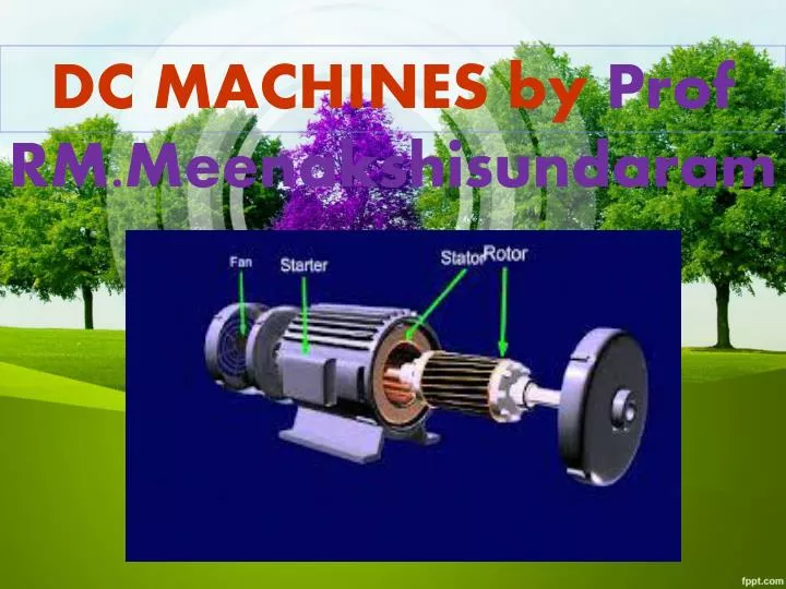
DC MACHINES by Prof RM.Meenakshisundaram. Maxwell’s Cork screw Rule :. Maxwell’s Cork screw Rule :.

E N D
Maxwell’s Cork screw Rule : Hold the cork screw in yr right hand and rotate it in clockwise in such a way that it advances in the direction of current. Then the direction in which the hand rotates will be the direction of magnetic lines of force .
Fleming’sleft hand rule Used to determine the direction of force acting on a current carrying conductor placed in a magnetic field . The middle finger , the fore finger and thumb of the left hand are kept at right angles to one another . • The middle finger represent the direction of current • The fore finger represent the direction of magnetic field • The thumb will indicate the direction of force acting on the conductor . This rule is used in motors.
Fleming’s Right hand rule • Used to determine the direction of emf induced in a conductor • The middle finger , the fore finger and thumb of the left hand are kept at right angles to one another. • The fore finger represent the direction of magnetic field • The thumb represent the direction of motion of the conductor • The middle finger will indicate the direction of the inducted emf . This rule is used in DC Generators
Len’s Law The direction of induced emf is given by Lenz’s law . According to this law, the induced emf will be acting in such a way so as to oppose the very cause of production of it . • e = -N (dØ/dt) volts
DC Generator Mechanical energy is converted to electrical energy Three requirements are essential 1. Conductors 2. Magnetic field 3. Mechanical energy
Working principle • A generator works on the principles of Faraday’s law of electromagnetic induction • Whenever a conductor is moved in the magnetic field , an emf is induced and the magnitude of the induced emf is directly proportional to the rate of change of flux linkage. • This emf causes a current flow if the conductor circuit is closed .
Commutator DC Machine
Construction of DC Generator Field system Armature core Armature winding Commutator Brushes
Armature winding There are 2 types of winding Lap and Wave winding Lap winding • A = P • The armature windings are divided into no. of sections equal to the no of poles Wave winding • A = 2 • It is used in low current output and high voltage. • 2 brushes
Fieldsystem It is for uniform magnetic field within which the armature rotates. Electromagnets are preferred in comparison with permanent magnets They are cheap , smaller in size , produce greater magnetic effect and Field strength can be varied
Field system consists of the following parts Yoke Pole cores Pole shoes Field coils
Armature core The armature core is cylindrical High permeability silicon steel stampings Impregnated Lamination is to reduce the eddy current loss
Commutator Connect with external circuit Converts ac into unidirectional current Cylindrical in shape Made of wedge shaped copper segments Segments are insulated from each other Each commutator segment is connected to armature conductors by means of a cu strip called riser. No of segments equal to no of coils
Carbon brush Carbon brushes are used in DC machines because they are soft materials It does not generate spikes when they contact commutator To deliver the current thro armature Carbon is used for brushes because it has negative temperature coefficient of resistance Self lubricating , takes its shape , improving area of contact
Carbonbrush Brush leads (pig tails) Brush rocker ( brush gear ) Front end cover Rear end cover Cooling fan Bearing Terminal box
EMF equation Let, • Ø= flux per pole in weber • Z = Total number of conductor • P = Number of poles • A = Number of parallel paths • N =armature speed in rpm • Eg = emf generated in any on of the parallel path
EMFequation Flux cut by 1 conductor in 1 revolution = P * φ Flux cut by 1 conductor in 60 sec = P φ N /60 Avg emf generated in 1 conductor = PφN/60 Number of conductors in each parallel path = Z /A Eg = PφNZ/60A
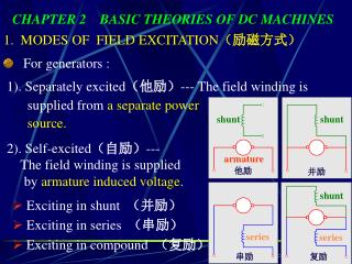
Types of DC Generator DC generators are generally classified according to their method of excitation . • Separately excited DC generator • Self excited D C generator
Further classification of DC Generator • Series wound generator • Shunt wound generator • Compound wound generator • Short shunt & Long shunt • Cumulatively compound & Differentially compound
Characteristics • No load saturation characteristic (Eo/If) • Internal or Total characteristic (E/ Ia) • External characteristic (V/I)
Critical field resistance For appreciable generation of emf, the field resistance must be always less certain resistance, that resistance is called as the critical resistance of the machine .
General terms used in Armature reaction Magnetic neutral axis : It is perpendicular to the lines of force between the two opposite adjacent poles. Leading pole Tip (LPT) : It is the end of the pole which first comes in contact with the armature. Trailing pole tip : It is the end of the pole which comes in contact later with the armature.
Armature Reaction Interaction of Main field flux with Armature field flux
Effects of Armature Reaction • It decreases the efficiency of the machine • It produces sparking at the brushes • It produces a demagnetising effect on the main poles • It reduces the emf induced • Self excited generators some times fail to build up emf
Armature reaction remedies 1.Brushes must be shifted to the new position of the MNA 2.Extra turns in the field winding 3.Slots are made on the tips to increase the reluctance 4. The laminated cores of the shoe are staggered 5. In big machines the compensating winding at pole shoes produces a flux which just opposes the armature mmf flux automatically.
Commutation The change in direction of current takes place when the conductors are along the brush axis . During this reverse process brushes short circuit that coil and undergone commutation Due to this sparking is produced and the brushes will be damaged and also causes voltage dropping.
Losses in DC Generators 1. Copper losses or variable losses 2. Stray losses or constant losses Stray losses : consist of (a) iron losses or core losses and (b) windage and friction losses . Iron losses : occurs in the core of the machine due to change of magnetic flux in the core . Consist of hysteresis loss and eddy current loss. Hysteresis loss depends upon the frequency , Flux density , volume and type of the core .
Losses Hysteresis loss depends upon the frequency , Flux density , volume and type of the core . Eddy current losses : directly proportional to the flux density , frequency , thickness of the lamination . Windage and friction losses are constant due to the opposition of wind and friction .
Applications Shunt Generators: a. in electro plating b. for battery recharging c. as exciters for AC generators. Series Generators : A. As boosters B. As lighting arc lamps
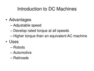
DC Motors Converts Electrical energy into Mechanical energy Construction : Same for Generator and motor Working principle : Whenever a current carrying conductor is placed in the magnetic field , a force is set up on the conductor.
Back emf The induced emf in the rotating armature conductors always acts in the opposite direction of the supply voltage . According to the Lenz’s law, the direction of the induced emf is always so as to oppose the cause producing it . In a DC motor , the supply voltage is the cause and hence this induced emf opposes the supply voltage.
Classification of DC motors DC motors are mainly classified into three types as listed below: • Shunt motor • Series motor • Compound motor • Differential compound • Cumulative compound
Torque The turning or twisting force about an axis is called torque . • P = T * 2 πN/ 60 • EbIa = Ta * 2 πN/ 60 • T ∞ φ I a • Ta ∞ I2a
Characteristic of DC motors • T/ Ia characteristic • N/ I a characteristic • N/T characteristic
Speed control of DC motors According to the speed equation of a dc motor N ∞ Eb/φ ∞ V- Ia Ra/ φ Thus speed can be controlled by- Flux control method: By Changing the flux by controlling the current through the field winding. Armature control method: By Changing the armature resistance which in turn changes the voltage applied across the armature
Flux control Advantages of flux control: • It provides relatively smooth and easy control • Speed control above rated speed is possible • As the field winding resistance is high the field current is small. Power loss in the external resistance is small . Hence this method is economical Disadvantages: • Flux can be increased only upto its rated value • High speed affects the commutation, motor operation becomes unstable
Armature voltage control method • The speed is directly proportional to the voltage applied across the armature . • Voltage across armature can be controlled by adding a variable resistance in series with the armature Potential divider control : If the speed control from zero to the rated speed is required , by rheostatic method then the voltage across the armature can be varied by connecting rheostat in a potential divider arrangement .
Starters for DC motors Needed to limit the starting current . 1. Two point starter 2. Three point starter 3. Four point starter
Testing of DC machines To determine the efficiency of as DC motor , the output and input should be known. There are two methods. • The load test or The direct method • The indirect method Direct method: In this method , the efficiency is determined by knowing the input and output power of the motor. Indirect method: Swinburne’s test is an indirect method of testing DC shunt machines to predetermine the effficency , as a motor and as a Generator. In this method, efficiency is calculated by determining the losses .