Download
1 / 61
610 likes | 613 Views
This paper discusses the design choices for high-performance circuits, focusing on the challenges in high-performance arithmetic units. It explores the use of SOI vs. bulk devices and presents case studies of 64-bit ALUs in PD-SOI and Bulk CMOS technologies. Energy-efficient high-performance AGUs and ALUs are also explored, along with the design of 4GHz Sparse-tree AGUs and 6.5-10GHz Integer ALUs. The paper concludes with a summary of the discussed trends.

E N D
Intel Labs High-Performance ArithmeticChallenges: From Architectures to Circuits Ram K. Krishnamurthy, Sanu K. Mathew, Shekhar Borkar Microprocessor Research, Intel Labs Intel Corporation, Hillsboro, OR, USA ramk@ichips.intel.com Prof. Vojin Oklobdzija ACSEL Lab, Dept. of ECE University of California, Davis, CA, USA vojin@ece.ucdavis.edu 16th IEEE International Computer Arithmetic Symposium, Santiago, June 18th 2003
Outline • Motivation • Design choices for high-performance circuits • SOI vs. Bulk devices: ALU design test-case • 64-bit ALUs in PD-SOI and Bulk CMOS • Energy-efficient high-performance AGU/ALUs • 4GHz Sparse-tree AGU Design • 6.5-10GHz Integer ALU Design • Summary
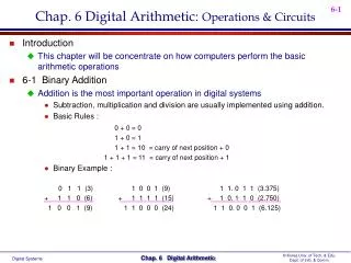
High-performance trends • Frequency doubles every generation • Performance-critical units • ALUs & AGUs • Register files, L0 caches Single-cycle latency & throughput
64-bit ALUs in 0.18mm PD-SOI/Bulk CMOS:Design & Scaling Trends [S. Mathew et al, ISSCC 2001] [S. Mathew et al, JSSC, Nov 2001]
Design choices • High performance devices: • Partially depleted Silicon-on-Insulator • Pros & Cons vs. bulk CMOS • Scaling trends • High performance circuit design: • Sparse-tree semi-dynamic AGU • Single-rail dynamic ALU
PD-SOI Devices p+ n+ n+ • Body of devices not tied to Vcc/Vss • Body is isolated by buried oxide • Floating Body! STI p+ n+ p+ P type body N type body STI STI Buried Oxide P-Substrate
History Effect in PD-SOI G S D n+ Gate • Delay = Function of switching history • Capacitive coupling from S/G/D • Impact Ionization, Diode conduction • Transient Vbs DC Vbs Cgb n+ Body Potential n+ Csb Cdb Buried Oxide Cbox Backgate Complicates timing analysis
64-bit ALU architecture Mux control Shift control External operands 5:1 Mux 0.5pF 9:1 Mux Single rail adder core 3:1 Mux Sum External operands 2:1 Mux 9:1 Mux Mux control Sign control 1200mmLoopback bus Ideal test-bed for evaluating process technologies
High-performance Adders: Kogge Stone 1 2 3 4 5 6 7 Sumeven Even input bits PG Gen. CM1 CM2 CM3 CM4 CM5 XOR Sumodd Odd input bits XOR CM1 CM2 CM3 CM4 CM5 PG Gen. GG=Gi+PiGi-1 GP=PiPi-1 • Generate all carries: • Full-blown binary tree energy-inefficient • # Carry-merge stages = log2(N)
64-bit Han-Carlson adder core PG generator 3N b59 b63 b62 b61 b60 b3 b2 b1 b0 Odd bit Even bit Carry-merge0 • Carry-merge done on even bitslices • 50% fewer carry-merge gates vs. Kogge-Stone • Extra logic stage generates odd carries 2P Carry-merge1 2N CM0 CM1 Carry-merge5 2N 2P Odd carry generator Sum XOR
Energy-efficient adder core 43% less energy/transition at iso-performance
Han Carlson carry-merge tree Complementary signal generator PG gen. CM0 CM1 CM2 CM3 CM4 CM5 CM6 Ceven Even inputs • Single rail adder core • CSG circuit generates dual-rail carry 2P CSG 2N 2N 3N 2P 2P 2N Ceven Codd Odd inputs CSG 2P 3N Codd Odd carry generator Carry-merge tree Dual rail Single rail
Complementary signal gen. • Domino-compatible Carry/Carry • Permits a single-rail carry-merge tree design • Not time-borrowable – Penalty absorbed by placing gate at F2 boundary F2 Keeper Carryi True pull-down path Cini Keeper Complementary pull-down path Carryi
Partial sum generator F1 F1 Pi • Generates domino-compatible partial sum • Placing the gate at F1 boundary mitigates output noise-glitches Ai Bi Keeper F1 Gi Psumi Ai Bi
ALU performance in bulk CMOS F1 F2 Adder core Inp. Sum 9:1 Mux 5:1 Mux 3:1 Mux Bus driver 1200mm Bus 2N 3N 2P 2P 2P 2N XOR 2P 2N 310ps 0.18mm bulk CMOS, Vcc=1.5V
Porting from bulk to PD-SOI Direct port SOI design • Design issues: • Noise tolerance due to lowered Vt • Min-delay timing-analysis Bulk design SOI-optimal design SOI favored redesign • Motivation for redesign: • Reduced SOI stack penalty • Deeper stack design • Stage reduction • Design choices: • Architecture should favor deep stack design • Avoid increase in fanouts
0.18mm Bulk & PD-SOI technologies • Equal IOFF at DC Vbs • SOI IDSAT is 1-2% lower
Direct port of Han-Carlson ALU to PD-SOI 0.18mm technology, Vcc=1.5V • Adder core speedup = 14% • [Stasiak et al.,ISSCC 2000] 21% speedup
Speedup analysis • Diffusion dominated muxes Max. speedup • Load dominated gates Speedup decreases
Motivation for PDSOI-optimal redesign • Reduced stack penalty in SOI • Deeper stack design Stage reduction • ALU is amenable to such a redesign • Not true for all CPU critical paths • SOI-optimal ALU architecture • Increasing stack depth must not increase fanouts • A novel deep-stack sparse-tree ALU was developed
Sparse-tree adder core 2N PG generator b63 b62 b61 b60 b3 b2 b1 b0 2P 7:6 5:4 3:2 59:58 63:62 61:60 1:0 • 50% reduced fanouts compared to Han-Carlson • 7 gate stages (Two less than Han-Carlson) 4N 39:32 31:24 23:16 15:8 47:40 7:0 Fast carry-merge tree 2P 15:0 31:16 47:32 3N 47:0 49:48 51:50 31:0 55:54 53:52 11:10 59:58 57:56 17:16 21:20 19:18 33:32 35:34 27:26 25:24 23:22 37:36 43:42 41:40 39:38 5:4 3:2 1:0 9:8 7:6 Mux Int. carry gen. Int. carry gen. Int. carry gen. Int. carry gen. Mux SumGen SumGen SumGen SumGen SumGen SumGen SumGen SumGen SumGen SumGen SumGen SumGen SumGen SumGen SumGen SumGen
Intermediate Carry Generator P7:4 G7:4 P3:0 G3:0 P11:8 G11:8 1 0 2 2 2 2 CM CM CM CM CM CM Carry from Fast CM Chain 2:1 Mux 2:1 Mux 2:1 Mux C3 C11 C7 • Generates 1 in 4 carries (C3, C7, C19….. C59) • Non-critical path (ripple carry-select scheme) • Fast carry selects bet. the conditional carries
Non-critical Sum Generator Pi+2 ,Gi+2 Gi+1 Pi Pi+3,Gi+3 Pi+1 1 0 CM CM CM CM CM CM Sumi ,1 Sumi ,0 XOR XOR XOR XOR XOR XOR Carry 2:1 2:1 2:1 2:1 Sumi+3 Sumi+1 Sumi+2 Sumi • Non-critical path: ripple carry chain • Reduced area, energy consumption, leakage • Generate conditional sums for each bit • 1 in 4 carry selects appropriate sum
Sparse-tree adder critical path Intermediate carry generator 3N 2P 2N • Fast carry-merge path Critical path • Non-critical side-paths Ripple-carry Input 2N 2P 4N 2P 3N Fast carry-merge path 2N Sumout 2P Inv 3N Sum generator
PD-SOI optimal redesign in 0.18mm 0.18mm technology, Vcc=1.5V Deeper stack redesign additional 5% speedup
Margining for reverse-body bias in PD-SOI • 400mV rvs. bias increases rise-delay by 10% • Difficult to detect for large circuits • 10% Margin required for all max-delay paths Overall PD-SOI speedup reduces to 11%
Reducing reverse-bias penalty in dynamic SOI gates P0 F A Body-A • Point solution for dynamic designs • Pre-charging stack node decreases penalty to 2% Cost 5% increase in clock energy M1 Stack node B Body-B Out A B Max-delay margin reduced to 2%
0.18mm ALU performance after margining 0.18mm technology, Vcc=1.5V Maximum PD-SOI speedup reduces to 19%
Scaling to 0.13mm technologies • Equal SOI & bulk IOFF-DC • MOSFET & impact ionization data obtained from 0.13mm bulk measurements • SOI parasitic BJT/diode characteristics unchanged from 0.18mm fitting
Scaling ALU designs to 0.13mm technology 0.13mm technology, Vcc=1.2V Maximum PD-SOI speedup reduces to 16%
SOI vs. bulk Summary • 482ps energy-efficient dynamic 64b ALU in 0.18mm bulk • 310ps adder core • Direct port to 0.18mm SOI 14%speedup • SOI optimal redesign 19%speedup • Floating body can get reverse-biased • Preconditioning reduces margin from 10% to 2% • Scaling to 0.13mm decreases PD-SOI speedup • Maximum PD-SOI speedup in 0.13mm falls to 16%
High-Performance Low Power Datapath design Energy Delay Goal: Shift the E-D curve
Intel Labs A 4GHz 130nm Address Generation Unit with 32-bit Sparse-tree Adder Core [S. Mathew et al, VLSI Symp. 2002], [S. Mathew et al, JSSC May 2003]
Motivation Cache Processor thermal map Temp (oC) Execution core AGU 120oC • AGUs: performance and peak-current limiters • High activity thermal hotspot • Goal: high-performance energy-efficient design
AGU Architecture 32 3:2 Compressor 32 Base 32 Effective Address 32b add 3b shift 32 32 Index clk3 32 clk2 Segment 32 clk + Displacement clk • Single-cycle latency and throughput • Effective Address = Base + Index*Scale + (Segment +Displacement) • 2-phase address computation
AGU Operation: Phase 1 32 3:2 Compressor 32 32 Base Effective Address 32b adder 32 3b shift 32 Index clk3 32 clk2 Segment 32 clk + Displacement Carry-Save format clk • Index pre-scaled via 3-bit barrel shifter • 3:2 compressor renders partial address: • Carry-save format • Adder in pre-charge state
AGU Operation: Phase 2 32 3:2 Compressor 32 32 Base Effective Address 32b adder 3b shift 32 32 Index clk3 32 clk2 Segment 32 clk + Displacement clk • Carry-save to binary format conversion: • 2’s complement parallel 32-bit adder
Kogge-Stone Adder PG 31 30 29 28 27 26 25 24 23 22 21 20 19 18 17 16 15 14 13 12 11 10 9 8 7 6 5 4 3 2 1 0 Carry-merge gates XOR • Critical path = PG+5+XOR = 7 gate stages • Generate,Propagate fanout of 2,3 • Maximum interconnect spans 16b Energy inefficient
Sparse-tree Adder Architecture • Generate every 4th carry in parallel • Side-path: 4-bit conditional sum generator • 73% fewer carry-merge gatesenergy-efficient
Non-critical Sum Generator Pi+2 ,Gi+2 Gi+1 Pi Pi+3,Gi+3 Pi+1 1 0 CM CM CM CM CM CM Sumi ,1 Sumi ,0 XOR XOR XOR XOR XOR XOR Carry 2:1 2:1 2:1 2:1 Sumi+3 Sumi+1 Sumi+2 Sumi • Non-critical path: ripple carry chain • Reduced area, energy consumption, leakage • Generate conditional sums for each bit • Sparse-tree carry selects appropriate sum
Optimized First-level Carry-merge Conditional Carry for Cin=0 0 CM Gi C#_0 • Carry-merge stage reduces to inverter • Conditional carry_0 = Gi#
Optimized First-level Carry-merge 1 Conditional carry for Cin=1 CM Pi C#_1 Gi Pi C#_1 • Pi & Gi correlated • Conditional carry_1 = Pi#
Optimized Sum Generator Pi+2 ,Gi+2 Gi+1 Pi+3,Gi+3 Pi+1 Pi Optimized 1st-level carry-merge CM CM CM CM Sumi ,1 Sumi ,0 XOR XOR XOR XOR XOR XOR Carry 2:1 2:1 2:1 2:1 Sumi+1 Sumi+3 Sumi Sumi+2 • Optimized non-critical path: 4 stages
Adder Core Critical Path clk3 clk clk2 Adder Inputs C27 PG GG1 GG3 GG7 GG15 GG27 Single-rail dynamic sparse-tree path Sum31_0 Sum31 CM0 Latch CM1 XOR clk Sum31_1 Static sum generator • Critical path: 7 gate stages same as KS • Sparse-tree: single-rail dynamic • Exploit non-criticality of sum generator • Convert to static logicSemi-dynamic design
1st-level Carry-merge: Static Latch • Holds state in pre-charge phase • Prevents pre-charging of static stages
Domino-Static Interface clk=0 clk=1 • Sum=Sum0 during pre-charge • Mux output resolves during evaluation
Sparse-tree Architecture • Performance impact: (20% speedup) • 33-50% reduced G/P fanouts • 80% reduced wiring complexity • 30% reduction in maximum interconnect • Power impact: (56% reduction) • 73% fewer carry-merge gates • 50% reduction in average transistor size
Energy-delay Space 100 130nm CMOS, 1.2V, 110oC Simulation 80 56% 60 Dynamic Kogge-Stone Worst-case Energy (pJ) 40 20% 20 4GHz Design Semi-dynamic Sparse-Tree 0 140 160 180 200 220 240 260 280 Delay (ps) • 20% speedup over Kogge-Stone • 56% worst-case energy reduction • Scales with activity factor
Semi-dynamic Design 40 Dynamic Kogge-Stone 30 71% Average Energy (pJ) 20 Semi-dynamic Sparse-Tree 10 0 0 0.1 0.2 0.3 0.4 0.5 Activity factor • Static sum generators : low switching activity • 71% lower average energy at 10% activity