Download
1 / 27
270 likes | 383 Views
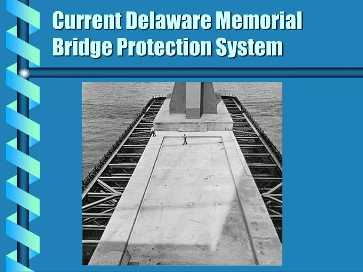
Current Delaware Memorial Bridge Protection System. Bridge Protection System. Team: 98.6 Members: Nikhil Bhate, Brandon Clark, Neil Smith, Scott Suhmann Direct Customer: Hardcore DuPont Composites, LLC Advisor: Dr. Jack Vinson

E N D
Bridge Protection System • Team: 98.6 • Members: Nikhil Bhate, Brandon Clark, Neil Smith, Scott Suhmann • Direct Customer: Hardcore DuPont Composites, LLC • Advisor: Dr. Jack Vinson • Mission: By the end of Spring Semester 1998, design, fabricate, and test a working unit section model of a bridge protection system that gives meaningful information towards replacing the current fender system on the Delaware Memorial Bridge. • Approach: Use Total Quality Design principles to provide a background for concept generation and evaluation.
Customers List: • Hardcore DuPont: • George Tunis, Dave Harris • Delaware River Bay Authority (DRBA): • Joe Volk, Rick Volk, Steve Moore • Delaware Pilot’s Association: • Captain Linton • Army Corps Of Engineers: • Governmental Agencies: • Construction Crew: • Other Ships and Vessels: • Maurice Richard, Tony Smith
Constraints: • Cannot Alter Bridge Foundation • Cannot Obstruct 1000 foot channel • Visible • No Creosols • No Lead Based Paints
Benchmarking • System Benchmarking • Protection Systems for smaller vessels • Camels, Fenders, Springs • Protection Systems for larger vessels • Sunshine Skyway Bridge, Golden Gate Bridge, Great Belt Easter Bridge
Benchmarking • Functional Benchmarking • Energy Absorbing Systems • Hex-Foam, Cushion Wall, Hexalite, Fluidic Shocks Hex-Foam Sandwich Cushion Wall
Concept Generation • Artificial Island • Stand Alone Dolphin System • Horizontal Piling Structure • Pile Supported Fender with Large Protective Cells
Artificial Island • Large island surrounding footing, made of any material • Easy to Construct • Difficult to apply composites
Dolphin System • Two or more composite walled structures filled with crushed stone or sea shells around footing • Prevents head-on impact • Too expensive to protect side impact
Horizontal Piling Structure • Filled Pilings arranged horizontally outward from footing. • Device attached to induce fracture inside piling on impact • Dissipates energy through fracture mechanics • Theory difficult to apply to ship impact • Destroyed during use
Pile Supported Fender with Protective Cells • Takes advantage of large protective cells for head on impact • Channel side protected by smaller fender structure • Uses composites to aid installation • Makes use of structural aspects of composite materials • Complex design
Concept Selection • Evaluated advantages and shortcomings of concepts through an iterative design process (SSD). • Pile Supported Fender System determined to be the best in terms of satisfying wants and metrics
Advantages of Design • Uses composites to reduce installation time • Composite adds structural advantages • Composite replaces rebar by taking tensile loads • Composite confines concrete eliminating the need for stirrups in support column
Concept Discussion • Choosing a design vessel: • An 80,000 ton ship was chosen
Concept Discussion • Vessel Speed and Orientation: • Using tactical diameter, depth conditions, and current flow data an angle of attack of 30°, and speed of 4 knots was calculated.
Design Details • Protective Cells: • 80 ft dia. • Situated at footing end to prevent head on collision • Composite sheath, filled with gravel, and capped with concrete
Support Columns 12 ft dia. 1” thick carbon glass hybrid pile Installed in sections Filled with concrete Assumed to be cantilevered at 500 year scour Design Details
Design Details • Support Column • Applied load: 1.11E6 lbs. • EI total: 2.17E13 lb.-in^2 • Base Bending Moment: 1.07E9 in-lb. • Tube tensile stress: 5.37E4 psi • Filler compression stress: 7.4E3 psi
Design Details • Fender • 20 ft. x 15 ft. x 36 ft. • Concrete encased with ‘bottle core’ composite • Cone at base for installation • Rebar used to distribute load to pile
Design Methodology • Design focus on support column and fender • Protective cell size benchmarked • Iterative design process for support column • analyzed diameters of 10 ft. to 14 ft. • determined the flexural rigidity of composite column with concrete filler
Testing • Tested to determine distribution factor due to the adjacent piles.
Costing • Concrete: $875,000 • Composites: • Protection Cell -- $400,000 • Support Columns -- $165,000 • Bottle Core Wall -- $3,750,00 • Total: $10.3 million • Labor: $9.5 million
Issues for Further Investigation • Further costing analysis • Connecting fender to end protection cells • Test a larger scale prototype for further proof of distribution factor.