Download
1 / 7
491 likes | 1.8k Views
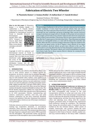
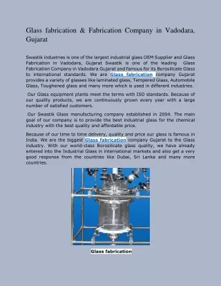
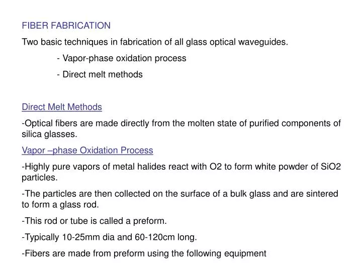
FIBER FABRICATION Two basic techniques in fabrication of all glass optical waveguides. - Vapor-phase oxidation process - Direct melt methods Direct Melt Methods Optical fibers are made directly from the molten state of purified components of silica glasses.

E N D
FIBER FABRICATION • Two basic techniques in fabrication of all glass optical waveguides. • - Vapor-phase oxidation process • - Direct melt methods • Direct Melt Methods • Optical fibers are made directly from the molten state of purified components of silica glasses. • Vapor –phase Oxidation Process • Highly pure vapors of metal halides react with O2 to form white powder of SiO2 particles. • The particles are then collected on the surface of a bulk glass and are sintered to form a glass rod. • This rod or tube is called a preform. • Typically 10-25mm dia and 60-120cm long. • Fibers are made from preform using the following equipment
Outside Vapor –phase oxidation • Loss less than 20dB/km • A layer of SiO2 particles called SOOT is deposited from a burner onto a rotating graphite. • The glass SOOT adheres to this bait rod and layer and layer, a cylindrical porous glass preform is build up. • By controlling the constituents of the metal halide vapor stream during the deposition process, the glass dimensions desired for the core and cladding can be incorporated into the preform. • When the deposition process is completed the mandral is removed and porous tube is then virtified in a dry atmosphere at high temperature to a clear glass preform. • This preform is mounted in a fiber drawing tower and made into a fiber.
Vapor-phase Axial Deposition • - SiO2 particles are formed in the same way. • These particles emerge from the torches they are deposited onto the end surface of a silica glass rod which acts as a seed. • A porous preform is grown in the axial direction by moving the rod upward. • The rod is also continuously rotated to maintain cylindrical symmetry of the particle deposition. • As the porous preform moves upward, it is transformed into a solid, transparent rod preform by melting with the carbon ring heater. • Modified Chemical Vapor Deposition • Pioneered at Bell laboratories • Low loss graded index fibers • The glass vapor particles , arising from the reaction of metal halide gases and oxygen flow through inside of silica tube. • As the SiO2 are deposited, they are sintered to clear glass layer which travel back and forth along the tube.
When the desired thickness of glass rod have been deposited, the vapor flow is shut off and tube is heated strongly to cause it to collapse into solid rod preform. • The fiber is drawn from this preform rod , core consists of vapor deposited material and cladding consists of original silica tube. • Plasma Activated Chemical Vapor Deposition: • Philips research invented • Similar to MCVP • A non isothermal microwave plasma operating at low pressure initiates the chemical reaction. • With the silica tube , a moving microwave resonator operating at 2.45GHz generates a plasma inside the tube to activate the chemical reaction. • This process deposits clear glass material directly on the tube wall. • No SOOT formation , no sintering is required. • When desired glass thickness is deposited , the tube is collapsed into a preform.
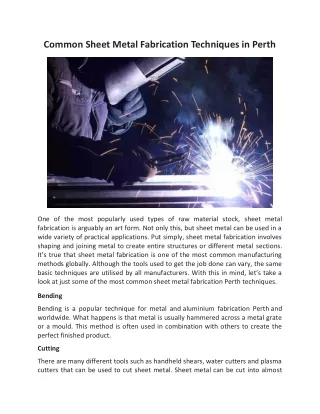
Double Crucible Method: • Silica, Chalgenide and halide glass fibers can be made. • Glass rods for the core and cladding materials are first made separately by melting mixtures of purified powders. • These rods are used as feedstock for each of two concentric crucibles. • The inner crucible contains the molten core glass and outer contains cladding glass. • The fibers are drawn from the molten state through orifices in the bottom of the two concentric crucibles in a continuous production process. • Attention must be paid to avoid contaminants arise from furnace environment and from the crucible.
MECHANICAL PROPERTIES OF OPTICAL FIBER • Fiber strength and durability • Optical fibers exclusively fabricated from silica or compound of glass. • Materials are brittle and exhibit perfect elasticity until their breaking point is reached. • Bulk material strength of flawless glass is quite high and estimated for individual materials using the relationship • St= (עpE/4la)1/2 • St= theoritical cohesive strength • עp= Surface energy of the material • E= Youngs modulus of the material • la=atomic space/bond distance • Bulk material strength reduced by the presence of surface flaws within the material. • In order to treat surface flaws in glass, the griffith theory is normally used.
This theory assumes that surface flaws are narrow cracks with small radii of curvature at their tips. • It postulates that the stress is concentrated at the tip of the crack which leads to crack growth. • Stress intensity factor • Ki=SYC1/2__________1 • S= macroscopic stress on the fiber • Y= constant • C= depth of the crack • Critical stress intensity factor where fracture occurs • Kic=(2Eעp)1/2______________2 • Combining 1 and 2 • S= [2Eעp/Y2C]1/2 • A primary protective coating is usually applied , mechanically induced flaws can be minimized. • Flaws also occur due to chemical and structural changes. • Another effect is stress corrosion, occurs bec of molecular bonds are attacked by water