Download
1 / 53
530 likes | 533 Views
This course provides an introduction to the mathematical foundations of computer graphics, including 2D and 3D geometry, trigonometry, vectors, and affine spaces. Learn the fundamental concepts and tools needed to model, animate, and render 3D scenes.

E N D
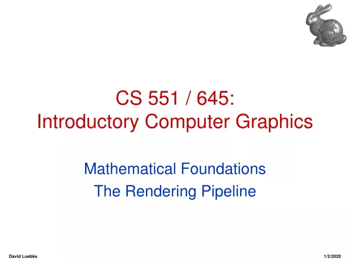
CS 551 / 645: Introductory Computer Graphics Mathematical Foundations The Rendering Pipeline David Luebke 1/2/2020
Administrivia • Sorry about the canceled class • OpenGL text: v1.1 or v1.2? • Teddy link fixed • Go over Assignment 1 David Luebke 1/2/2020
XForms Intro • Xforms: a toolkit for easily building Graphical User Interfaces, or GUIs • See http://www.westworld.com/~dau/xforms • Lots of widgets: buttons, sliders, menus, etc. • Plus, an OpenGL canvas widget that gives us a viewport or context to draw into with GL or Mesa. • Quick tour now • You’ll learn the details yourself in Assignment 1 David Luebke 1/2/2020
Mathematical Foundations • FvD appendix gives good review • I’ll give a brief, informal review of some of the mathematical tools we’ll employ • Geometry (2D, 3D) • Trigonometry • Vector and affine spaces • Points, vectors, and coordinates • Dot and cross products • Linear transforms and matrices David Luebke 1/2/2020
2D Geometry • Know your high-school geometry: • Total angle around a circle is 360° or 2π radians • When two lines cross: • Opposite angles are equivalent • Angles along line sum to 180° • Similar triangles: • All corresponding angles are equivalent • Corresponding pairs of sides have the same length ratio and are separated by equivalent angles • Any corresponding pairs of sides have same length ratio David Luebke 1/2/2020
Trigonometry • Sine: “opposite over hypotenuse” • Cosine: “adjacent over hypotenuse” • Tangent: “opposite over adjacent” • Unit circle definitions: • sin () = x • cos () = y • tan () = x/y • Etc… (x, y) David Luebke 1/2/2020
3D Geometry • To model, animate, and render 3D scenes, we must specify: • Location • Displacement from arbitrary locations • Orientation • We’ll look at two types of spaces: • Vector spaces • Affine spaces • We will often be sloppy about the distinction David Luebke 1/2/2020
Vector Spaces • Two types of elements: • Scalars (real numbers): a, b, g, d, … • Vectors (n-tuples):u, v, w, … • Supports two operations: • Addition operation u + v, with: • Identity 0v + 0 = v • Inverse -v + (-v) = 0 • Scalar multiplication: • Distributive rule: a(u + v) = a(u) + a(v) (a + b)u = au + bu David Luebke 1/2/2020
Vector Spaces • A linear combination of vectors results in a new vector: v= a1v1 + a2v2 + … + anvn • If the only set of scalars such that a1v1 + a2v2 + … + anvn = 0 is a1 = a2 = … = a3 = 0 then we say the vectors are linearly independent • The dimension of a space is the greatest number of linearly independent vectors possible in a vector set • For a vector space of dimension n, any set of n linearly independent vectors form a basis David Luebke 1/2/2020
u+v y v u x Vector Spaces: A Familiar Example • Our common notion of vectors in a 2D plane is (you guessed it) a vector space: • Vectors are “arrows” rooted at the origin • Scalar multiplication “streches” the arrow, changing its length (magnitude) but not its direction • Addition uses the “trapezoid rule”: David Luebke 1/2/2020
Vector Spaces: Basis Vectors • Given a basis for a vector space: • Each vector in the space is a unique linear combination of the basis vectors • The coordinates of a vector are the scalars from this linear combination • Best-known example: Cartesian coordinates • Draw example on the board • Note that a given vector v will have different coordinates for different bases David Luebke 1/2/2020
Vectors And Points • We commonly use vectors to represent: • Points in space (i.e., location) • Displacements from point to point • Direction (i.e., orientation) • But we want points and directions to behave differently • Ex: To translate something means to move it without changing its orientation • Translation of a point = different point • Translation of a direction = same direction David Luebke 1/2/2020
Affine Spaces • To be more rigorous, we need an explicit notion of position • Affine spaces add a third element to vector spaces: points (P, Q, R, …) • Points support these operations • Point-point subtraction: Q - P = v • Result is a vector pointing fromPtoQ • Vector-point addition: P + v = Q • Result is a new point • Note that the addition of two points is not defined Q v P David Luebke 1/2/2020
Affine Spaces • Points, like vectors, can be expressed in coordinates • The definition uses an affine combination • Net effect is same: expressing a point in terms of a basis • Thus the common practice of representing points as vectors with coordinates (see FvD) • Analogous to equating pointers & integers in C • Be careful to avoid nonsensical operations David Luebke 1/2/2020
Affine Lines: An Aside • Parametric representation of a line with a direction vector d and a point P1 on the line: P(a) = Porigin + ad • Restricting 0aproduces a ray • Setting d to P - Q and restricting 0a 1 produces a line segment between P and Q David Luebke 1/2/2020
Dot Product • The dot product or, more generally, inner product of two vectors is a scalar: v1 • v2 = x1x2 + y1y2 + z1z2 (in 3D) • Useful for many purposes • Computing the length of a vector: length(v) = sqrt(v • v) • Normalizing a vector, making it unit-length • Computing the angle between two vectors: u • v = |u| |v| cos(θ) • Checking two vectors for orthogonality • Projecting one vector onto another v θ u David Luebke 1/2/2020
Cross Product • The cross product or vector product of two vectors is a vector: • The cross product of two vectors is orthogonal to both • Right-hand rule dictates direction of cross product David Luebke 1/2/2020
Linear Transformations • A linear transformation: • Maps one vector to another • Preserves linear combinations • Thus behavior of linear transformation is completely determined by what it does to a basis • Turns out any linear transform can be represented by a matrix David Luebke 1/2/2020
Matrices • By convention, matrix elementMrc is located at row r and column c: • By (OpenGL) convention, vectors are columns: David Luebke 1/2/2020
Matrices • Matrix-vector multiplication applies a linear transformation to a vector: • Recall how to do matrix multiplication David Luebke 1/2/2020
Matrix Transformations • A sequence or composition of linear transformations corresponds to the product of the corresponding matrices • Note: the matrices to the right affect vector first • Note: order of matrices matters! • The identity matrixI has no effect in multiplication • Some (not all) matrices have an inverse: David Luebke 1/2/2020
Transform Illuminate Transform Clip Project Rasterize The Rendering Pipeline: A Whirlwind Tour Model & CameraParameters Rendering Pipeline Framebuffer Display David Luebke 1/2/2020
Transform Illuminate Transform Clip Project Rasterize The Display You Know Model & CameraParameters Rendering Pipeline Framebuffer Display David Luebke 1/2/2020
Transform Illuminate Transform Clip Project Rasterize The Framebuffer You Know Model & CameraParameters Rendering Pipeline Framebuffer Display David Luebke 1/2/2020
Transform Illuminate Transform Clip Project Rasterize The Rendering Pipeline • Why do we call it a pipeline? Model & CameraParameters Rendering Pipeline Framebuffer Display David Luebke 1/2/2020
Transform Illuminate Transform Clip Project Rasterize 2-D Rendering: Rasterization(Coming Soon) Model & CameraParameters Rendering Pipeline Framebuffer Display David Luebke 1/2/2020
Transform Illuminate Transform Clip Project Rasterize The Rendering Pipeline: 3-D Model & CameraParameters Rendering Pipeline Framebuffer Display David Luebke 1/2/2020
The Rendering Pipeline: 3-D Scene graphObject geometry • Result: • All vertices of scene in shared 3-D “world” coordinate system • Vertices shaded according to lighting model • Scene vertices in 3-D “view” or “camera” coordinate system • Exactly those vertices & portions of polygons in view frustum • 2-D screen coordinates of clipped vertices ModelingTransforms LightingCalculations ViewingTransform Clipping ProjectionTransform David Luebke 1/2/2020
The Rendering Pipeline: 3-D Scene graphObject geometry • Result: • All vertices of scene in shared 3-D “world” coordinate system • Vertices shaded according to lighting model • Scene vertices in 3-D “view” or “camera” coordinate system • Exactly those vertices & portions of polygons in view frustum • 2-D screen coordinates of clipped vertices ModelingTransforms LightingCalculations ViewingTransform Clipping ProjectionTransform David Luebke 1/2/2020
Rendering: Transformations • So far, discussion has been in screen space • But model is stored in model space(a.k.a. object space or world space) • Three sets of geometric transformations: • Modeling transforms • Viewing transforms • Projection transforms David Luebke 1/2/2020
Y X Z Rendering: Transformations • Modeling transforms • Size, place, scale, and rotate objects parts of the model w.r.t. each other • Object coordinates world coordinates Y Z X David Luebke 1/2/2020
Rendering: Transformations • Viewing transform • Rotate & translate the world to lie directly in front of the camera • Typically place camera at origin • Typically looking down -Z axis • World coordinates view coordinates David Luebke 1/2/2020
Rendering: Transformations • Projection transform • Apply perspective foreshortening • Distant = small: the pinhole camera model • View coordinates screen coordinates David Luebke 1/2/2020
¢ q - q é ù é ù é ù X cos sin X = ê ú ê ú ê ú ¢ q q Y sin cos Y ë û ë û ë û Rendering: Transformations • All these transformations involve shifting coordinate systems (i.e., basis sets) • That’s what matrices do… • Represent coordinates as vectors, transforms as matrices • Multiply matrices = concatenate transforms! David Luebke 1/2/2020
Rendering: Transformations • Homogeneous coordinates: represent coordinates in 3 dimensions with a 4-vector • Denoted [x, y, z, w]T • Note that w = 1 in model coordinates • To get 3-D coordinates, divide by w:[x’, y’, z’]T = [x/w, y/w, z/w]T • Transformations are 4x4 matrices • Why? To handle translation and projection David Luebke 1/2/2020
Rendering: Transformations • OpenGL caveats: • All modeling transforms and the viewing transform are concatenated into the modelview matrix • A stack of modelview matrices is kept • The projection transform is stored separately in the projection matrix • See Chapter 3 of the OpenGL book David Luebke 1/2/2020
The Rendering Pipeline: 3-D Scene graphObject geometry • Result: • All vertices of scene in shared 3-D “world” coordinate system • Vertices shaded according to lighting model • Scene vertices in 3-D “view” or “camera” coordinate system • Exactly those vertices & portions of polygons in view frustum • 2-D screen coordinates of clipped vertices ModelingTransforms LightingCalculations ViewingTransform Clipping ProjectionTransform David Luebke 1/2/2020
Rendering: Lighting • Illuminating a scene: coloring pixels according to some approximation of lighting • Global illumination: solves for lighting of the whole scene at once • Local illumination: local approximation, typically lighting each polygon separately • Interactive graphics (e.g., hardware) does only local illumination at run time David Luebke 1/2/2020
The Rendering Pipeline: 3-D Scene graphObject geometry • Result: • All vertices of scene in shared 3-D “world” coordinate system • Vertices shaded according to lighting model • Scene vertices in 3-D “view” or “camera” coordinate system • Exactly those vertices & portions of polygons in view frustum • 2-D screen coordinates of clipped vertices ModelingTransforms LightingCalculations ViewingTransform Clipping ProjectionTransform David Luebke 1/2/2020
Rendering: Clipping • Clipping a 3-D primitive returns its intersection with the view frustum: • See Foley & van Dam section 19.1 David Luebke 1/2/2020
Rendering: Clipping • Clipping is tricky! In: 3 vertices Out: 6 vertices Clip In: 1 polygon Out: 2 polygons Clip David Luebke 1/2/2020
Transform Illuminate Transform Clip Project Rasterize The Rendering Pipeline: 3-D Model & CameraParameters Rendering Pipeline Framebuffer Display David Luebke 1/2/2020
Modeling: The Basics • Common interactive 3-D primitives: points, lines, polygons (i.e., triangles) • Organized into objects • Collection of primitives, other objects • Associated matrix for transformations • Instancing: using same geometry for multiple objects • 4 wheels on a car, 2 arms on a robot David Luebke 1/2/2020
Modeling: The Scene Graph • The scene graph captures transformations and object-object relationships in a DAG • Objects in black; blue arrows indicate instancing and each have a matrix Robot Head Body Mouth Eye Leg Trunk Arm David Luebke 1/2/2020
Modeling: The Scene Graph • Traverse the scene graph in depth-first order, concatenating transformations • Maintain a matrix stack of transformations Robot Visited Head Body Unvisited Leg Mouth Eye Trunk Arm MatrixStack Active Foot David Luebke 1/2/2020
Modeling: The Camera • Finally: need a model of the virtual camera • Can be very sophisticated • Field of view, depth of field, distortion, chromatic aberration… • Interactive graphics (OpenGL): • Pinhole camera model • Field of view • Aspect ratio • Near & far clipping planes • Camera pose:position & orientation David Luebke 1/2/2020
Modeling: The Camera • These parameters are encapsulated in a projection matrix • Homogeneous coordinates 4x4 matrix! • See OpenGL Appendix F for the matrix • The projection matrix premultiplies the viewing matrix, which premultiplies the modeling matrices • Actually, OpenGL lumps viewing and modeling transforms into modelview matrix David Luebke 1/2/2020
Rigid-Body Transforms • Goal: object coordinatesworld coordinates • Idea: use only transformations that preserve the shape of the object • Rigid-body or Euclidean transforms • Includes rotation, translation, and scale • To reiterate: we will represent points as column vectors: David Luebke 1/2/2020
Vectors and Matrices • Vector algebra operations can be expressed in this matrix form • Dot product: • Cross product: • Note: useright-handrule! David Luebke 1/2/2020
Translations • For convenience we usually describe objects in relation to their own coordinate system • Solar system example • We can translate or move points to a new position by adding offsets to their coordinates: • Note that this translates all points uniformly David Luebke 1/2/2020