Download
1 / 14
270 likes | 908 Views
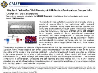
Application: Anti-Reflective Coatings. Your eyeglasses (possibly) and sophisticated multi-element optical systems like telephoto lenses (definitely) rely on anti-reflective coatings to reduce extraneous images, loss of contrast, and other image degradation due to unwanted reflections.

E N D
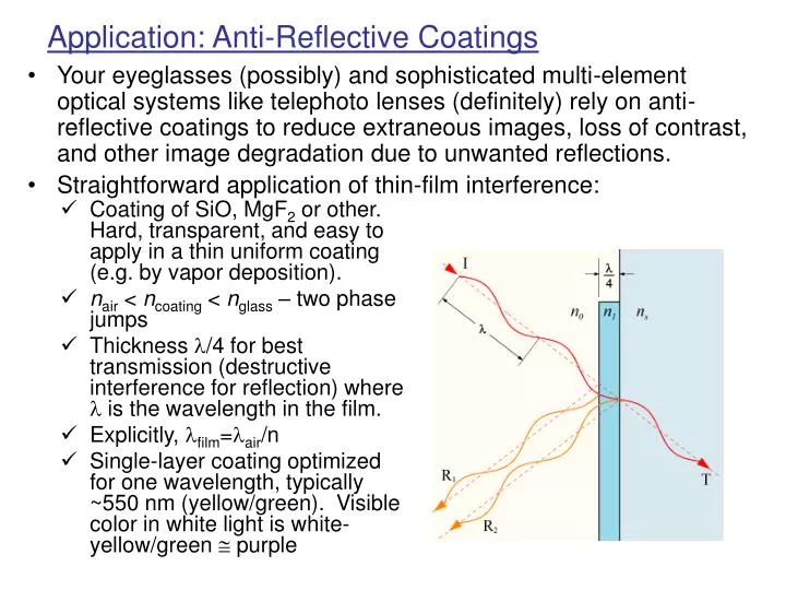
Application: Anti-Reflective Coatings • Your eyeglasses (possibly) and sophisticated multi-element optical systems like telephoto lenses (definitely) rely on anti-reflective coatings to reduce extraneous images, loss of contrast, and other image degradation due to unwanted reflections. • Straightforward application of thin-film interference: • Coating of SiO, MgF2 or other. Hard, transparent, and easy to apply in a thin uniform coating (e.g. by vapor deposition). • nair < ncoating < nglass – two phase jumps • Thickness /4 for best transmission (destructive interference for reflection) where l is the wavelength in the film. • Explicitly, lfilm=lair/n • Single-layer coating optimized for one wavelength, typically ~550 nm (yellow/green). Visible color in white light is white-yellow/green purple
x z E = cB y How is the energy of an incident wave shared between reflected and transmitted waves at a boundary? • Derivable from Maxwell’s equations and physical boundary conditions on the E and B fields. Polarized along x. Propagating toward +z. Normally incident on boundary at z = z0 between region 1 (n1) and region 2 (n2). Apply these to a harmonic EM wave crossing this bdy.
Example: - Air(n1=1) Lucite(n2=1.5) R2=.04 T2=.96 Analysis is similar, but more complicated, for non-normal incidence Fresnel formulas.
Interferometer: sensitive instrument that can measure physical parameters that change the phase of a wave. Path length (distance), refractive index, motion with respect to wave medium,… Michelson’s interferometer produces interference fringes by splitting a monochromatic beam, sending the two parts along different paths, and recombining to form an interference pattern. One path has a movable mirror (the other has a fixed one). Precise distance measurements are made by moving the mirror and counting the number m of interference fringes that pass a reference and determining the distance as d = m/2. Michelson Interferometer Demonstration: Michelson Interferometer
Diffraction • More of the same! Interference in different circumstances. • News flash: Light does not really propagate like a geometrical ray or simple particle. • Demonstration: Laser and Diffraction Objects • In coherent, monochromatic, light, razor blades cast fuzzy shadows, pinholes produce interference fringes, and solid spheres appear to have holes….
The “Poisson Spot” The center of the shadow is the only point that is equidistant from every point on the circumference, so there must be constructive interference.
Diffraction around knife edges, through slits and pinholes, and in other circumstance were studied extensively by Fresnel, both experimentally and by Huygens construction. “Fresnel Diffraction” is the general case, with full detailed analysis and diffraction patterns that depend on distance from the obstacle. “Fraunhofer Diffraction” refers to the simplified case where the light source and observation point are both far from the obstacle, so that plane waves can be assumed and rays taken to be parallel. This is the approximation we use. (Essentially the small-angle approximation we used before.)
Assume coherent, monochromatic waves. Waves through S1 interfere constructively with those through S2 when d sin = n (n = 0, 1, 2,…) Waves from S2 interfere constructively with those from S2 when d sin = n (n = 0, 1, 2,…) The maxima overlap, but the minima are more complicated. When S1 and S2 cancel, S3 is left over. Full cancellation occurs when S1+S2 cancels S3 or S2+S3 cancels S1. Full cancellation occurs when there is a 120 (or 240 or…) phase spacing of the waves from the sources. P S1 d S2 d S3 Two slits were nice, how about three? Multiple-Slit Interference
Full intensity analysis Observed intensity pattern Principal Maxima Secondary Maxima Demonstration: Multiple Slits
Diffraction Grating Principal maxima: d sin = m (m = 0, 1, 2,… is the “order”) Minima: d sin = m /N (m = 0, 1, 2,… as above, with m = N, 2N,… are excluded) We didn’t go through this exercise because we care about 3 slits!N parallel slits makes a
Diffraction Grating – Intensity Distribution Intensity (from superposition of fields): Imax = N2I0 <I> = NI0 Width of maxima: = /(N d) (sharper for big N) Principal Maxima As N gets bigger, the maxima get sharper • What does a diffraction grating do with white light? • Each wavelength gets its own set of principal maxima at characteristic angles. • White light is dispersed into its component wavelengths – a spectrum like that from dispersion, only better. Secondary maxima are negligible for a real grating with N of thousands.
Demonstration: Projected Spectra with Grating • Anyone have a diffraction grating? • A CD/DVD is an inadvertent reflection grating • A real diffraction grating is a plate of optical glass, ruled with thousands of parallel grooves, or a plastic cast of a ruled glass grating. With light passing through you have a transmission grating and with a coating of aluminum you get a reflection grating.