Download
1 / 27
290 likes | 567 Views
SLAC KLYSTRON LECTURES Lecture 14 June 23, 2004 2-D and 3-D MAGIC Simulation Software Applied to Klystron Design Examples David Smithe and Larry Ludeking ATK Mission Research magic@mrcwdc.com George Caryotakis, Glenn Scheitrum, Daryl Sprehn, and Bob Steele

E N D
SLAC KLYSTRON LECTURES Lecture 14 June 23, 2004 2-D and 3-D MAGIC Simulation Software Applied to Klystron Design Examples David Smithe and Larry Ludeking ATK Mission Research magic@mrcwdc.com George Caryotakis, Glenn Scheitrum, Daryl Sprehn, and Bob Steele Stanford Linear Accelerator Center
Outline • Example of Klystron Simulation in MAGIC Software • Overview of FD-TD-PIC Computation Method • Various Different Uses for the Software • The B-Factory Klystron Template • Challenges for the Future
Geometry-Based Simulation Example: 7 Cavity Klystron Voltage at Input Cavity Voltage at Output Cavity (Courtesy of SLAC)
Klystron Output Cavity Example • Penultimate and 5-stage output cavity. • Beam is bunched in several previous cavities. • (Magic 2D, simulation courtesy of SLAC.) [click for movie]
Theoretical Basis of MAGIC2D and MAGIC3D • Maxwell’s Equations • There are electromagnetic vector fields as a function of position, E(r), B(r), D(r), H(r), and particle current and charge fields, J(r), and r(r). • Initial Conditions: D = r B = 0 • Constitutive Relations: E = D / eH = B / m • Evolution Equations: tB = -EtD = H-J • Relativistic Lorentz Force • There are particles with position vector, xi, and relativistic momentum-per-mass vector, pi. • Velocity Relation: gi = (1+|pi / c|2)½vi = pi / gi • Evolution Equations: txi = vitpi = (qi/mi) [ E(xi) + vi Bi(xi) ]
Theoretical Basis of MAGIC2D and MAGIC3D (cont.) • Plus Many-Many Model Equations • Materials (e, s, and m, perfect conductors, polarizers, foils, films, etc.) • Boundary conditions (periodic, absorbing, transmission line, etc.) • Particle Emission models (thermionic, secondary, explosive, etc.) • Lumped circuit elements (resistor, inductor, cable, capacitor, etc.) • Static magnetic fields (coils, imported from other codes, etc.) • RF sources (voltage ports, current drivers, etc.) • Initial conditions (field solver, particle populations, etc.) • Feedback circuits
Time Domain Simulation • MAGIC is simulation, not analysis. The goal is to mimic nature, with as little “a priori” knowledge as possible. As with nature, one starts with an initial system state, and evolves the system forward in time, without prejudice as to what the future system will or should look like. Diagnostics allow the researcher to observe the system, and if fortunate, interpret what is happening in a physical sense. • This is Time Domain. So MAGIC Is FD-TD-PIC. • Simulation is essentially a metal-less laboratory. • Example: If a device must be properly tuned in a real laboratory, then it will need to be similarly tuned in simulation. • Example: If a device can’t work in the laboratory, it will be very difficult, or hopefully impossible, to force it to work somehow in simulation. • Example: If the lab results are confusing, the simulation results might also be confusing. But, of course, MAGIC has diagnostics no lab has!
Field components are [Edl], [DdA/dt], [Hdl], and [BdA/dt]. All derivatives, x , , and “t,” become matrices with 0,±1. Matrix Formulation Divergence of B: Gauss’s Law: Continuity: Faraday’s Law: Ampere’s Law: Material Properties:
Uses for Simulation Software • General qualitative understanding of physical processes • Evaluation of difficult-to-predict parameters for spreadsheet analysis • Plasma wave-number • Trans-conductance • Beam Loading, real and imaginary parts • Evaluation of difficult-to-analyze components • Penultimate and Output Cavities • Magnetic focusing of time-dependent bunched-beam • Entire end-to-end simulation
Qualitative Understanding • Many special diagnostics allow one to visualize the physics, and better understand it • Example: bunch behavior in an SBK output cavity • It is usually simple to try unusual geometry or situations, once the basic geometry is in place • Example: one absent beam line in an MBK [click for movie]
Parameter Evaluation - Plasma Wavenumber • Excite cavity, pass steady-state beam through it, and watch bunching develop as beam passes through long drift tube. Tells where to place next cavity. ¼ lp
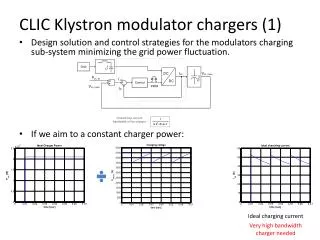
Parameter Evaluation – Beam Loading • Ring-down Simulation. Pump up cavity with beam present, turn off pump. Signal will decay, giving Qbeam. Oscillation will also shift frequency slightly to beam loaded frequency. Beam Loaded Frequency
Difficult Components – Output Cavity • In the output cavity • Small-signal analysis is no longer valid • Particles in bunches may overtake one-another • Space charge forces are accentuated because of tight bunching • Radial transport is significant • Extended interaction regions imply more than one possible mode • Coupler geometry may be significant • Simulation is almost a necessity • Example: ¾ - p mode output cavity [click for movie]
Sheet Beam Output Cavity • Uses 3-cavity extended interaction, coupler load in 3rd cavity end only • Example: Checking for constant phase across width of sheet beam [click for movie]
Difficult Components – Acceleration of Bunched Beam • Klystron-like device, called a Reltron. • Two stages of DC voltage applied • Input cavity between the stages [click for movie]
The B-Factory Klystron Template • Pre-written MAGIC2D input file of complete klystron, for public use • Find it in Vacuum Electronics book by Barker et al. • Find it at SLAC website • User-friendly interface allows novices to redesign aspect of the klystron including cavity frequencies, Q’s, spacings, and gap parameters.
The template allows one to load previous results. The design iterative process is a repetition of device tuning runs, followed by a full-up hot-test run for result. Template Design and Optimization Capability
Template Cavity Parameters • Dialogs allow specification of all major cavity parameters
Template Tuning Results • Results of each iteration are tracked, and error between actual and desired values is given.
Template Hot Test Setup • Hot test parameters are set in a dialogue box
Template Hot Test Run • PHASESPACE plots during the hot test run show qualitative behavior
Results are provided in graphics and tabular form. Template Hot Test Results
Challenges for the Future – Problem Size • Simulation Geometry • Always need more cells in 3-D • Example: Multiple Beam Klystron • Parallel processing will help. Non-Uniform Grid Grid resolution of Beam Tubes 12 cells across tube.
Challenges for the Future – Relativistic Devices • Numerical Cerenkov instability remains a manageable nuisance • HIGH_Q algorithm damps instability without loading cavities • Grid “jiggling” allows standard un-damped algorithms • Still looking for more convenient solutions to the problem.
Challenges for the Future – Maintaining Reliability • SLAC has developed an HTML driven Automated Test Suite to allow fast verification of MAGIC results on a large suite of different test cases. • Provides quick verification of new versions of the software.
Summary • The MAGIC software has been used for studying klystrons at SLAC for at least 8 years. • As computer speed increases, the potential uses of the software have evolved from 2-D physics studies to 3-D design work. • This talk has provided an overview and many examples of the use of the MAGIC software in klystron problems. • An public klystron template, based on SLAC’s B-factory klystron is available for use, experimentation, and education. • Parallel processing capability and active software development programs offer promise for even more capability in the future.