Download
1 / 24
240 likes | 440 Views
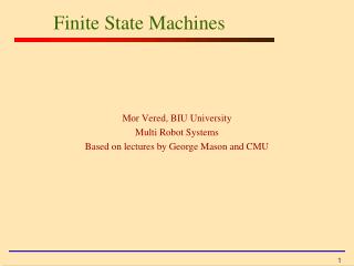
ECE2030 Introduction to Computer Engineering Lecture 16: Finite State Machines. Prof. Hsien-Hsin Sean Lee School of Electrical and Computer Engineering Georgia Tech. MEALY MACHINE. MOORE MACHINE. Inputs X(t). Outputs Z(t). Inputs X(t). Combinational circuits. Combinational circuits.

E N D
ECE2030 Introduction to Computer EngineeringLecture 16: Finite State Machines Prof. Hsien-Hsin Sean Lee School of Electrical and Computer Engineering Georgia Tech
MEALY MACHINE MOORE MACHINE Inputs X(t) Outputs Z(t) Inputs X(t) Combinational circuits Combinational circuits Storage Element S(t) Storage Element S(t) Outputs Z(t) Z(t) = {S(t), X(t)} Z(t) = {S(t)} Mealy and Moore Machines
State and State Diagram • A state represents the machine snapshot at a given clock period • A clock is typically used to synchronize the state transition • A graph consists of a set of • Circles: • Each represents a state • Use double circle to represent the initial state • Directed arc: each represents a state transition • Inputs/outputs • Mealy machine: • Label input/output along each arc • Moore machine: • Label input along each arc • Label output inside the circle (i.e. state)
a/p a b Sk Sj Sk/p Sj/q b/p a/q a b/q b State Diagrams A Mealy machine example A Moore machine example Example: State: S(t) {Sk, Sj} Inputs: X(t) {a, b} Outputs: Z(t) {p, q} Initial state: S(0) = Sk
0/0 S0 S1 1/0 0/0 1/1 0/0 0/0, 1/1 S1 S0 1/0 State Diagram Examples (Mealy)
0 0, 1 S0/0 S1/1 1 State Diagram Examples (Moore) 0 S0/1 S1/0 1 0 1
Design Example: Sequence Recognizer • A sequential circuit that recognizes the occurrence of a particular bit sequence • Input: X(t) {0, 1} • Output: Z(t) {0, 1}
Sequence Recognizer Time 0 1 2 3 4 5 6 7 8 9 10 11 12 13 14 15 16 X(t) 1 0 0 1 0 1 1 0 1 0 1 1 0 1 1 0 1 Z(t) 0 0 0 0 0 0 0 0 1 0 0 0 0 1 0 0 1
S1 S2 S3 Sequence Recognizer Time 0 1 2 3 4 5 6 7 8 9 10 11 12 13 14 15 16 X(t) 1 0 0 1 0 1 1 0 1 0 1 1 0 1 1 0 1 Z(t) 0 0 0 0 0 0 0 0 1 0 0 0 0 1 0 0 1 1/1 1/0 0/0 1/0 S0 1/0 0/0 0/0 0/0 A Meanly Machine
State Table 1/1 1/0 0/0 1/0 00 01 10 11 1/0 0/0 0/0 0/0
Logic Circuits Design Steps • Generate a Boolean function for • Each external output • Each state encoded bit • Simplify the Boolean functions • Draw a D F/F (or register) for each state encoded bit • Draw logic circuits for • External outputs • Each inputs of state encoded bits • Input of state encoded bits = the next state • Output of state encoded bits = the current state
Logic Circuits Design N1 P1P0 X N0 P1P0 X
X D0 F/F D0 F/F N0 N0 P0 P0 1 1 2 2 Z D1 F/F N1 P1 1 2 Logic Circuits Design
Example 2 • Input: X(t) {a, b, c} • Output: Z(t) {q, p}
c SEE/p SOO/p SOE/p a State Diagram b a b c C SEO/q b b a c a A Moore Machine
b a b c C 01/q b b a c a c 00/p 10/p 11/p a State Table SEE = 00 SEO = 01 SOO = 10 SOE = 11 a = 00 b = 01 c = 10 p = 0 q = 1
Logic Circuit Design N1 X1X0 P1P0 N0 X1X0 P1P0 Z X1X0 P1P0
D0 F/F N0 P0 1 2 Z X0 D1 F/F N1 P1 1 2 Logic Circuit Design X1
Vending Machine State Machine • Dispense a Coke when depositing 15 ¢ • Inputs • 5 = a nickel • 10 = a dime • BC = bad coin (including quarters in this example) • Outputs • R = reject • C = coke • N = no coke
5/N 5 ¢ 10/C 5/C 10/C 10/N 5/N 10 ¢ State Diagram BC/R 0 ¢ BC/R BC/R
10/C 5/C 10/C 5/N State Table 5/N BC/R 0 ¢ (00) 5 ¢ (01) BC/R 10/N 10 ¢ (10) BC/R 5: 00 10: 01 BC: 10 N: 00C: 01 R: 10
Logic Circuits Design N1 X1X0 P1P0 N0 X1X0 P1P0
Logic Circuits Design C1 X1X0 P1P0 C0 X1X0 P1P0
X1 X0 P1 P0 D0 F/F N0 P0 1 2 D1 F/F N1 P1 1 2 C0 C1 Logic Circuits of the Vending Machine