Download
1 / 41
630 likes | 1.18k Views
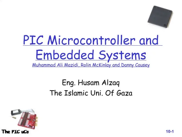
PIC Microcontroller and Embedded Systems Muhammad Ali Mazidi, Rolin McKinlay and Danny Causey. Eng. Husam Alzaq The Islamic Uni. Of Gaza. Chapter 6: Bank Switching, Table processing, Macros and Modules.

E N D
PIC Microcontroller and Embedded SystemsMuhammad Ali Mazidi, Rolin McKinlay and Danny Causey Eng. Husam Alzaq The Islamic Uni. Of Gaza
Chapter 6: Bank Switching, Table processing, Macros and Modules PIC Microcontroller and Embedded SystemsMuhammad Ali Mazidi, Rolin McKinlay and Danny Causey, February 2007.
Objective List all addressing modes of PIC18 uCs Contrast and compare the addressing modes Code PIC18 instructions to manipulate a lookup table. Access fixed data residing in ROM space. Discuss how to create macros and models, and its advantages. Discuss how to access the entire 4kB of RAM List address for all 16 banks of the PIC18 Discuss bank switching for the PIC18
Outlines Immediate and Direct Addressing mode Register indirect Addressing mode Lookup table and table processing Bit addressability of data RAM Bank switching Checksum and ASCII subroutines Macros and models
Introduction • Data could be in • A register • In memory • Provided as an immediate values • PIC18 provides 4 addressing modes • Immediate • Direct • Register indirect • Indexed-ROM
Section 6.1: Immediate and Direct Addressing mode • In immediate addressing mode, the operands comes after the opcode • MOVLW 0x25 • SUBLW D’34’ • ADDLW 0x86 • In direct addressing mode, the operand data is in a RAM location whose address is known and given as a part of the instruction.
Figure 6-1. MOVFF and MOVWF Direct Addressing Opcode MOVLW 0X56 MOVWF 0X40 MOVFF 0X40,50H
Figure 6-1. MOVFF and MOVWF Direct Addressing Opcode MOVLW 0X56 MOVWF 0X40 MOVFF 0X40,50H
Immediate and Direct Addressing mode • What is the difference between • INCF fileReg, W • INCF fileReg, F • What is the default destination? • What is the difference between DECFSZ and DECF? • Operation • Branch
SFR Registers and their addresses • Can be access by • Their name • Their address • Which is easier to remember? • MOVWF PORTB • MOVWF 0xF81
SFR Registers and their addresses Remember Notes In .lst file, you will see that the SFR names are replaced with thire addresses. The WREG register is one of the SFR registers and has address FE8h • SFR addresses is started at F80h and the last location has the address FFFh
Section 6.2: Register indirect Addressing mode FSR means file Select register • A register is used as a pointer to the data RAM location. • Three 12-bit Registers are used (from 0 to FFFh) • FSR0 • FSR1 • FSR2 • Each register is associated with INDFx • Syntax • LFSR n,data LFSR 1,95Eh needs 2 cycles
Advantages of Register indirect Addressing mode • It makes accessing data dynamic • Looping is possible to increment the address • Not possible in direct addressing mode • Example • INCF FSR2L
Example 6-2 Solution A MOVLW 0x55 MOVWF 0x40 MOVWF 0x41 MOVWF 0x42 MOVWF 0x43 MOVWF 0x44 • Write a program to copy the value 55H into RAM locations 40h to 45h using • Direct addressing mode • Register indirect addressing mode • A loop
Example 6-2 (cont.) Solution B Solution C COUNT EQU 0x10 MOVLW 0x5 MOVWF COUNT LFSR 0,0x40 MOVLW 0x55 B1 MOVWF INDF0 INCF FSR0L,F DECF COUNT,F BNZB1 MOVLW 55H LFSR 0,0x40 MOVWF INDF0 INCF FSR0L,F MOVWF INDF0 INCF FSR0L,F MOVWF INDF0 INCF FSR0L,F MOVWF INDF0 INCF FSR0L,F MOVWF INDF0
Auto increment option for FSR FSR0H FSR0L FF 03 • Normal increment can cause problem since it increments 8-bit • INC FSR0L, F • Auto increment and auto decrement solve the problem • They doesn’t affect the status flag
Example 6-4 Solution COUNTREG EQU 0x10 CNTVAL EQU D'16' MOVLW CNTVAL MOVWF COUNTREG LFSR 1,0x60 B3 CLRF POSTINC1 DECF COUNTREG,F BNZB3 • Write a program to clear 16 RAM location starting at location 60H using Auto increment. • Note: there are two identical mistakes in your book, pp 202. The right correction is FSR1=60H (not 40H)
Example 6-5 Solution COUNTREG EQU 0x10 CNTVAL EQU D'5' MOVLW CNTVAL MOVWF COUNTREG LFSR 0, 0x30 LFSR 1, 0x60 B3 MOVF POSTINC0,W MOVWF POSTINC1 DECF COUNTREG,F BNZB3 • Write a program to copy a block of 5 bytes of data from location starting at 30H to RAM locations starting at 60H.
Example 6-6 Solution COUNTREG EQU 0x20 L_BYTE EQU 0x06 H_BYTE EQU 0x07 CNTVAL EQU 4 MOVLW CNTVAL MOVWF COUNTREG LFSR 0,0x40 CLRF WREG CLRF H_BYTE B5 ADDWF POSTINC0, W BNCOVER INCF H_BYTE,F OVER DECF COUNTREG,F BNZB5 MOVWF L_BYTE • Assume that RAM locations 40-43H have the following hex data. Write a program to add them together and place the result in locations 06 and 07.
Example 6-7 Solution COUNTREG EQU 0x20 CNTVAL EQU D'4' MOVLW CNTVAL MOVWF COUNTREG LFSR 0,0x30 LFSR1,0x50 LFSR 2,0x60 BCF STATUS,C B3MOVF POSTINC0,W ADDWFC POSTINC1,W DAW MOVWF POSTINC2 DECF COUNTREG,F BNZB3 • Write a program to add the following multi-byte BCD numbers and save the result at location 60H. 12896577 + 23647839
Section 6.4: bit addressability of data RAM • One of the basic feathers of the PIC18 is the bit addressability of RAM. • Bit-addressable instructions • Use only direct addressing mode • Byte-addressable instructions
Status Register Bit-addressability • You can access any bit of the status register by their name. • Examples BCF STATUS,C BTFSS STATUS, Z
Section 6.5: Bank switching in the PIC18 • PIC18 has maximum of 4K of RAM • Not all the space used. • The fileReg is divided into 16 banks of 256B each • Every PIC18 has the access bank (the first 128B of RAM + SFR ) • Most PIC18 that access the data space in RAM has the ability to access any bank through setting an optional operand, called A • Example: MOVWF myReg, A • If 0 it access the default bank (default) • If 1, it uses the bank selection register (BSR) to select the bank
The BSR register and bank switching • It is 8-bit register • 4 bits are used 16 banks • Banks 0 (from 00 to FF) • Banks 1 (from 100 to 1FF) • Banks 2 (from 200 to 2FF) • ..... • Banks F (from F00 to FFF) (includes SFR) • Upon power-on reset, BSR is equal to 0 (default value)
A Bit in the Instruction Field for INCF F, D, A • Two thing must be done • Load BSR with desired bank • Make A = 1 in the instruction itself. MYREG EQU 0x40 MOVLB 0x2 MOVLW 0 MOVWF MYREG,1 INCF MYREG, F, 1 INCF MYREG, F, 1 INCF MYREG, F, 1
Example 6-25 • Write a program to copy the value 55H into RAM locations 340h to 345h using • Direct addressing mode • A loop MOVLB 0x3 MOVLW 0x55 MOVWF 0x40, 1 MOVWF 0x41, 1 MOVWF 0x42, 1 MOVWF 0x43, 1 MOVWF 0x44, 1 MOVWF 0x44, 1
Example 6-25 • Write a program to copy the value 55H into RAM locations 340h to 345h using • Direct addressing mode • A loop COUNT EQU 0x10 MOVLB 0x3 MOVLW0x6 MOVWF COUNT LFSR 0,0x340 MOVLW 0x55 B1 MOVWF INDF0,0 INCF FSR0L DECF COUNT,F,0 BNZB1
Section 6.6: Checksum and ASCII subroutines • To ensure the integrity of ROM contents, every system must perform a checksum calculation. • Corruption (caused by current surge) • To calculate the checksum byte • Add the bytes and drop the carries • Take the 2’s complement of the total sum • To perform the checksum operation • Add all bytes, including the checksum byte • The result must be zero, else error
Example 6-29 • Find the checksum byte 25H + 62H + 3FH + 52H 118H (Drop the carry bit) The 2’s comp. is E8 • Perform the checksum 25H + 62H + 3FH + 52H + E8H 200 (Drop the carry)
Example 6-29 • If the second byte 62H has been changed into 22H. Show how the checksum method detects the error. 25H + 22H + 3FH + 52H + E8H 1C0H (Drop the carry bit)
Section 6.7: Macros and models Body Unique • Dividing a program into several models allows us to use models in other application. • Reduce time • Reduce of errors • Increase the code size every time it invoked • MACRO Syntax Name MACRO dummy1, dummy2 … ……………. ……………. ENDM
Example: • Write a delay macro and a MOVLF macro. #include P18F458.INC NOEXPAND DELAY_1MACRO V1, TREG LOCAL BACK MOVLW V1 MOVWF TREG BACKNOP NOP NOP NOP DECF TREG,F BNZBACK ENDM Local decleration
Example, cont. MOVLFMACRO K, MYREG MOVLW K MOVWF MYREG ENDM ORG 0 CLRF TRISB OVERMOVLF 0x55,PORTB DELAY_1 0x200,0x10 MOVLF 0xAA,PORTB DELAY_1 0x200,0x10 BRAOVER END
Figure 6-12. List File with EXPAND Option for Program 6-4 (cont.)
Next: Chapter 9 Arithmetic, logic Instruction and programs Chapter 6: Summary