Download
1 / 36
370 likes | 389 Views
Overview of Inertial Fusion Energy Technology Activities. Mark Tillack. 1. Overview of IFE activities in the US 2. Overview of IFE activities at UCSD 3. Optics damage studies at UCSD. July 3, 2001 CIEMAT, Madrid. IFE research is coordinated between several distinct program elements.

E N D
Overview of Inertial Fusion Energy Technology Activities Mark Tillack 1. Overview of IFE activities in the US 2. Overview of IFE activities at UCSD 3. Optics damage studies at UCSD July 3, 2001 CIEMAT, Madrid
IFE research is coordinated between several distinct program elements
OFES R&D focuses on two chamber types HYLIFE-II: Thick-Liquid-Wall Chamber SOMBRERO: Dry-Wall Chamber Different scales First wall radius: HYLIFE-II = 3.5 m SOMBRERO = 6.5 m • Georgia Institute of Technology (GT) • Idaho National Environmental & Engineering Lab (INEEL) • Lawrence Livermore National Laboratory (LLNL) • Oak Ridge National Laboratory (ORNL) • University of California: • Berkeley (UCB), Los Angeles (UCLA), San Diego (UCSD) • University of Wisconsin – Madison (UW)
IFE chamber research funded by OFES • Dry-wall chamber research • Thick-liquid-wall chamber research • Driver/chamber interface • heavy-ion drivers • laser drivers • IFE safety and environmental studies
Dry-wall chambers: key features and issues Low pressure (< 0.5 Torr), high-Z gas (Xe) protects first wall from short-ranged target emissions Low activation structures (C/C composites and/or SiC) Flowing Li2O granules serve as breeder and coolant Modular blanket for ease of replacement Suited for direct-drive targets Key Issue: Chamber Lifetime. Can the first wall be protected from x-ray and debris damage? Can first wall and blanket structures tolerate the effects of neutron damage for an acceptably long time and be designed for economical replacement? SOMBRERO
Thick-liquid-wall chambers: key features and issues HYLIFE-II Thick liquid “pocket” shields chamber structures from neutron damage and reduces activation Oscillating jets dynamically clear droplets near target No blanket replacement required, increases chamber availability Suited for indirect-drive targets Key Issue: Chamber Clearing.Can the liquid pocket and beam port protection jets be made repetitively without interfering with beams? Will vapor condensation, droplet clearing and flow recovery occur fast enough to allow pulse rates of ~ 6 Hz?
Injector manifolds Main flibe pocket jets Crossing jets for beam ports Final focus magnets Shielding and vacuum pumping Driver/chamber interface: heavy ion drivers Key Issue: Self-consistent design. Can superconducting final focusing magnet arrays be designed consistent with chamber and target solid angle limits for the required number of beams, standoff distance to the target, magnet dimensions and neutron shielding thickness? HYLIFE-II with ~ 200 beams
Driver/chamber interface: laser drivers Two primary options are being considered for the final optic: • Grazing incidence metal mirrors • Transmissive refractive optics Grazing incidence mirrors Key Issue: Protection and survival. Can final optics be adequately protected from x-rays, debris and dust and survive laser and neutron damage for more than one year before replacement? Will final optics have sufficient mechanical stability under pulsed operation to maintain the required pointing accuracy for target tracking? Si2O or CaF2 wedges
Flow between volumes considers friction, form losses and chocking Considers non-condensible gas effects Leak Filtered Dried Heat transfer to structures Conservation of mass, momentum and energy for both liquid and vapor phases Aerosol transport and deposition Suppression pools, heat exchangers, valves, pumps, etc. Schematic of MELCOR Capabilities Safety and environmental studies Key Issues: Power Plants: Can a level of safety be achieved so that a public evacuation plan is not required (< 10 mSv (1 rem) site boundary dose) for credible accident scenarios? Thick-Liquid-Wall Chambers: Can radioactive hohlraum materials be recovered from flibe and recycled in new targets? Dry-Wall Chambers: Can replaced chamber materials be recycled to minimize annual waste volumes? Can tritium retention in candidate materials (C/C composites, SiC) be maintained at an acceptable level?
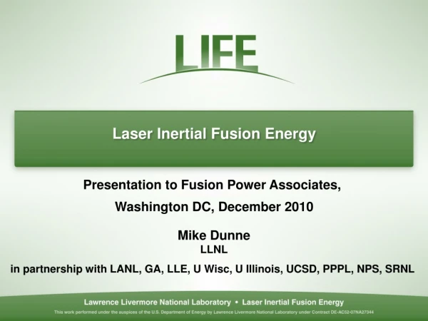
Goals of the High Average Power Laser Program Long term goal: Develop science & technologies required for Inertial Fusion Energy Focussed on direct drive with lasers Builds upon recent advances in target design & lasers Complementary technologies (target fab/injection, chambers, final optics) Short term goal: Science & technologies for a rep-rate laser/target/chamber system for DP needs Study detailed properties of matter relevant to DP Rep-rate allows extremely accurate and flexible experiments Complement high energy single shot facilities Achieving these goals requires development as a coherent, integrated system Spin offs: Advanced laser technologies Robust, high damage threshold optics Advanced pulsed power systems Target/ chamber/ final optics development for the NIF Development of directed energy technologies High quality science
The elements of the High Average Power Laser Program 2. Target Fabrication GA: Fab, charac, mass production LANL: Adv mat, target fab, DT inventory Schafer: Foams, cryo layering 1. Direct Drive Target Designs NRL- Nike Program LLNL: Yield spectrum Wisconsin- Yield spectrum Target factory 3. Target Injection GA: Injector, Injection & Tracking LANL: Materials prop, thermal resp. 4. Lasers NRL: KrF (gas) Laser LLNL: (DPSSL) 6. Chambers Wisconsin: Dry wall, safety, integrate design LLNL: Other walls, target yield, neut damage UCSD: Chamber clearing, materials SNL et al: Materials resp to x-rays & ions 5. Final Optics LLNL: X-rays, ions, debris, neut. UCSD: Laser damage, debris mit LANL: Neutrons on optics
The Mercury dpssl laser (LLNL): 100 J, 1.05 mm, 10 Hz, 2-10 ns, 10% laser for IFE-related experiments Diode pulsers Front end Gas-cooled amplifier head Pump delivery Injection multi-pass spatial filter
Overview of Inertial Fusion Energy Technology Activities at UC San Diego Mark Tillack http://joy.ucsd.edu July 3, 2001 CIEMAT, Madrid
Driver Interface R&D: Beam Propagation Problem Statement • The chamber environment following a target explosion contains a hot, turbulent gas which will interact with subsequent laser pulses. • Gas breakdown occurs in the vicinity of the target where the beam is focussed. • A better understanding of the degree of gas ionization and the effects on beam propagation are needed. • The effect of aerosol and particulate in the chamber must be understood in order to establish clearing criteria. Research Objectives: • Determine the laser breakdown threshold in pure and impure chamber environments at low pressure. • Determine the effect of chamber environmental conditions on beam propagation.
Beam propagation experiments will be performed in a multi-purpose vacuum chamber under construction Key Program Elements • Construction of a multi-purpose vacuum chamber • Breakdown emission detection and spectroscopy • Laser beam smoothing and accurate profiling (goal of 2-5%) Initial measurements: • Visible light emission from the focal spot • Variation in laser energy profile (CCD) & temporal pulse shape (photodiodes) • Wavefront variation (Shack-Hartmann) Planned future measurements: • Emission spectroscopy • Changes in spatial profile with 2% accuracy
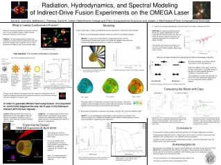
Chamber Physics Modeling and Experiments Problem Statement The chamber condition following a target explosion in a realistic chamber geometry is not well understood. The key uncertainty is whether or not the chamber environment will return to a sufficiently quiescent and clean low-pressure state to allow another shot to be initiated within 100–200 ms. Modeling and experimental capabilities are needed to predict the behaviour of an IFE power plant chamber and to ensure that all relevant phenomena are taken into account. Objectives • Develop and benchmark an integrated, state-of-the-art computational model of the dynamic response of IFE chambers following target explosions • Use the code to plan experiments and study IFE chambers • Demonstrate validity of scaling and simulation experiments • Develop chamber experimental capabilities • Provide new data relevant to IFE chamber responses
Chamber Physics Simulation Experiments Energy required to simulate IFE chamber issues HYADES simulation of laser irradiation of Au
Engineering Modeling of IFE Targets Input Parameters Initial target configuration Properties database Imposed accelerations Thermal environment Chamber gas, aerosol and particulate species Chamber hydrodynamic environment Computed Parameters Target temperature distribution Target trajectory Target internal stress distribution Internal mass transport In-hohlraum beta layering analysis:
IFE Wall Engineering ESLI carbon fiber flocked surface Structured surfaces may offer superior thermal response and improved erosion behavior under exposure to pulsed energy sources RHEPP/MAP ion beam facility, SNLA
Studies of Laser Induced Damageto Grazing Incidence Metal Mirrors Mark Tillack http://joy.ucsd.edu July 3, 2001 CIEMAT, Madrid
Geometry of the Driver-Chamber Interface (20 m) Grazing incidence mirrors (30 m) (SOMBRERO values in red) Prometheus-L reactor building layout Si2O or CaF2 wedges
Final Optic Damage Threats Final Optic Threat Nominal Goal Optical damage by laser >5 J/cm2 threshold (normal to beam) Sputtering by ions Wavefront distortion of <l/3 * (~100 nm) Ablation by x-rays (6x10⁸ pulses in 2 FPY: (~25 mJ/cm2, partly stopped by gas) 2.5x10⁶ pulses/allowed atom layer removed) Defects and swelling induced by Absorption loss of <1% g-rays (~3) and neutrons (~18 krad/s) Wavefront distortion of < l/3 * Contamination from condensable Absorption loss of <1% materials (aerosol and dust) >5 J/cm2 threshold Two main concerns: • Damage that increases absorption (<1%) • Damage that modifies the wavefront – • spot size/position (200mm/20mm) and spatial uniformity (1%) *“There is no standard theoretical approach for combining random wavefront distortions of individual optics. Each l/3 of wavefront distortion translates into roughly a doubling of the minimum spot size.” (Ref. Orth)
GIMM development issues* Experimental verification of laser damage thresholds Wavefront issues: beam smoothness, uniformity, shaping, f/number constraints Experiments with irradiated mirrors Protection against debris and x-rays (shutters, gas jets, etc.) In-situ cleaning techniques Large-scale manufacturing Cooling * from Bieri and Guinan, Fusion Tech. 19 (May 1991) 673.
Aluminum is the 1st choice for the GIMM Normal incidence reflectivity of metals • Lifetime of multi-layer dielectric mirrors is questionable due to rapid degradation by neutrons• Al maintains good reflectivity into the UV• Al is a commonly used mirror material – easy to machine, easy to deposit• Thin (~10 nm), protective, transparent oxide • Normal incidence damage threshold ~0.2 J/cm2• Grazing incidence raises s-reflectivity to >99%• Larger footprint reduces fluence by cos(q)• Combined effects hopefully raise the damage threshold to >5 J/cm2
Several surface types have been fabricated Al 1100 75 nm Al on superpolished flat: ±2Å roughness, 10Å flatness 99.999% pure Al diamond-turned Al 6061 MgSi occlusions
UCSD Laser Plasma and Laser-Material Interactions Laboratory Spectra Physics laser: 2J, 10 ns @1064 nm 700, 500, 300 mJ @532, 355, 266 nm Peak power~1014 W/cm2 Profiling Shack-Hartmann Q ~ 200 mrad
Ringdown reflectometry is used for accurate measurements and in-situ surface monitoring 100 ppm accuracy
In-situ reflectometry can measure surface changes not visible to the naked eye
Al 1100 shows no apparent damage up to 1 J/cm2 Several shots in Al 6061 at 80˚, 1 J/cm2 peak 1000 shots in Aal 1100 at 85˚, 1 J/cm2 peak MgSi Fe Fe 1000x 1000x • Damage occurs at a higher fluence as compared with normal incidence• Silicide occlusions in Al 6061 preferentially absorb light, causing explosive ejection and melting• Fe impurities appear unaffected• Exposure of Al 1100 to 1000 shots at 85˚ exhibited no damage
Tools for modeling effects of damage on beam characteristics
metal substrate n4, k4 coating n3, k3 n2, k2 contaminant n1, k1 q1 Incident medium Effect of Surface Coatings and Contaminants 4-layer Fresnel model was developed to examine behavior of coatings and contamination Surface contaminants (such as carbon) on mirror protective coatings can substantially alter reflectivity, depending on layer thickness and incident angle. d2=0 q1 = 80o d2=0 q1 = 0o 80o 60o reflectivity reflectivity d2=2 nm q1 = 80o 40o lo = 532 nm Al2O3 coating (10 nm) Al mirror 20o lo = 532 nm Carbon film Al mirror d2=2 nm q1 = 0o q1 = 0o Al2O3 coating thickness, d3/lo Carbon film thickness (nm)
The effect of induced surface roughness on beam quality was investigated using Kirchhoff wave scattering theory Isc q2 q1 Specularly reflected intensity is degraded by induced mirror surface roughness For cumulative laser-induced and thermomechanical damages, we assume Gaussian surface height statistics with rms height s. 1.0 0.8 0.6 0.4 0.2 0 Iinc q1 = 80o Intensity Degradation, e–g 70o 60o Io : reflected intensity from smooth surface Id : scattered incoherent intensity g : (4ps cosq1/l)2 e.g., at q1 = 80o, s/l = 0.1, e-g = 0.97 0 0.1 0.2 0.3 0.4 0.5 s / l • Grazing incidence is less affected by surface roughness • To avoid loss of laser beam intensity, s / l < 0.01
University of California, San Diego School of Engineering Graduate Studies in Plasma Physics & Controlled Fusion Research Current Research Areas: • Theoretical low temperature plasma physics • Experimental plasma turbulence and transport studies • Theoretical edge plasma physics in fusion devices • Plasma-surface interactions • Diagnostic development • Semiconductor manufacturing technology • Theory of emerging magnetic fusion concepts • Fusion power plant design and technology • Radio-frequency heating and current drive • Laser-matter interactions and inertial confinement fusion • Thermo-mechanical design of nuclear fusion reactor components • Theoretical space and astrophysical applications Interested students are encouraged to visit our website at: http://www-ferp.ucsd.edu/brochure.html for information on our research, available financial support and university admissions policy.