Download
1 / 28
280 likes | 401 Views
MARTE/CCSL, TimeSquare & K-Passa A design platform using MoCCs for embedded model-based engineering. C. André, J. Boucaron, A. Coadou, J. DeAntoni , B. Ferrero, F. Mallet, R. de Simone AOSTE Project INRIA/I3S Sophia Antipolis, France. Context.

E N D
MARTE/CCSL,TimeSquare & K-PassaA design platform using MoCCs for embedded model-based engineering C. André, J. Boucaron, A. Coadou, J. DeAntoni, B. Ferrero, F. Mallet, R. de Simone AOSTE Project INRIA/I3S Sophia Antipolis, France
Context • Modeling environments for real-timeembedded and distributed systems
Context • Modeling environments for real-timeembedded and distributed systems • Conceptual diagrammatic representations • Structural • Components / interactions • Dynamics/Behavior
Context • Modeling environments for real-timeembedded and distributed systems • Conceptual diagrammatic representations • Structural • Components / interactions • Dynamics/Behavior of individual components • State-based control flow • Activity-based data flow • Constrained programs with “same” expressivity
Context • Modeling environments for real-timeembedded and distributed systems • Conceptual diagrammatic representations • Structural • Components / interactions • Dynamics/Behavior of individual components • State-based control flow • Activity-based data flow • Constrained programs with “same” expressivity • Dynamics/Behavior of system • results from combining component behaviors according to structure
Example of architecture modeling Structure Behavior
Example of architecture modeling Structure Behavior
Example of architecture modeling Structure Elaboration phase (SystemC) Behavior Simulation
Traditional component approach • Structure • Black-box + Interfaces (Ports, Data Types) • Behavioral abstraction • Messages + possibly period and performance requirements • What we find missing: • Detailed definition of timing and synchronization properties • Communication protocol requirements • This missing information is often deported elsewhere
Traditional component approach • Structure • Black-box + Interfaces (Ports, Data Types) • Behavioral abstraction • Messages + possibly period and performance requirements • What we find missing: • Detailed definition of timing and synchronization properties • Communication protocol requirements • This missing information is often deported elsewhere
Logical functional time Functional: sequence of reaction steps Multiple times (local / global) Synchronization primitives → constraints between local activation times Synthesis / Compilation Process networks (SDF), synchronous reactive formalisms, statecharts “physical” time Extra functional Single time (total order) Timing constraints to be satisfied at execution Simulation semantics possibly different from synthesis UML, SystemC Time & Semantics
Logical functional time Functional: sequence of reaction steps Multiple times (local / global) Synchronization primitives → constraints between local activation times Synthesis / Compilation Process networks (SDF), synchronous reactive formalisms, statecharts “physical” time Extra functional Single time (total order) Timing constraints to be satisfied at execution Simulation semantics possibly different from synthesis UML, SystemC Time & Semantics HDLs
Logical functional time Functional: sequence of reaction steps Multiple times (local / global) Synchronization primitives → constraints between local activation times Synthesis / Compilation Process networks (SDF), synchronous reactive formalisms, statecharts “physical” time Extra functional Single time (total order) Timing constraints to be satisfied at execution Simulation semantics possibly different from synthesis UML, SystemC Semantics Our choice
MARTE: Time model and CCSL MARTE = Modeling and Analysis of Real-Time and Embedded systems • OMGUML profile (adopted June 2009) • Time subprofile (defined by us) • Rich but well-defined variety of time notions (logical/physical, discrete/dense, …) • Clockscan be explicitly attached to most UML model elements → timed semantics • Clock ConstraintSpecification Language (CCSL) • Various constraints on clocks (synchronous, asynchronous, mixed) • Precise formal semantics
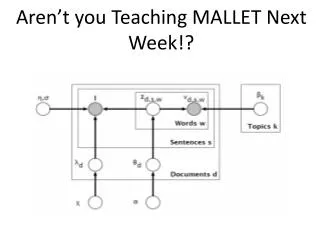
Why CCSL? • Polychronous system modeling • Specification of sophisticated synchronizations • Notation to describe semantic relations between timed behaviors (illustrated below) • Means to define formally timedModels of Computations and Communications (MoCCs) • Akin to Tagged Systems(Lee & Sangiovanni-Vincentelli)
Why CCSL? • Means to define formally timedModels of Computations and Communications (MoCCs) • In the sequel, we translate a MoCC as UML models + CCSL specifications • The chosen MoCC is SDF (weighted event graphs) models
incoming src dest Synchronous DataFlow SDF Meta-model • Nodes are called actors • Input/Output have a weight (Number of data samples consumed/produced) • Arcs have a delay
Synchronous DataFlow • Actor enabling = each incoming arc carries at least weight tokens • Actor execution = atomic consumption/production of tokens by an enabled actor • i.e., consume weight tokens on each incoming arcs and produce weight tokens on each outgoing arc • Delay is an initial token load on an arc. SDF firing rules: How can CCSL express this semantics?
SDF Example Evolutions of the model A A B A A B Static schedule: C C
How to model SDF graphs in UML ? Is that compatible with the UML semantics ? CCSL makes the semantics explicit … … within the model
SDF Actor A Token T Input i Output o CCSL Clock A; Clock write, read; Var delay:int; Var weight:int; Var weight:int; SDF semantics with CCSL (1/2)
SDF semantics with CCSL (2/2) • SDF • CCSL
AOSTE’s Tools • TimeSquare • Software environment dedicated to the • Specification of CCSL constraints • Resolution of CCSL constraints • Simulation and generation of trace model • Animation of UML models • Exploration of augmented timing diagrams • K-Passa • Computation of static schedules for specific MoCCs • Marked Graphs, Synchronous DataFlow, Latency-Insensitive Designs, K-periodical Routed Graphs • Analysis (deadlock freeness, safety) • Optimization (latency, throughput, interconnect buffer size) • Code generation (stand-alone simulator)
Tool download • http://www-sop.inria.fr/aoste/