Download

1 / 27
270 likes | 409 Views
P12022: LVAD Power Transmission Test Rig. Erin McNally Pedro Baez Paul Parthemore Kris Stichter. Table of Contents. Background Information Customer Needs Engineering Specifications Preliminary Design Proposed Design GUI Design DAQ Specifications Feasibility Analysis BOM

E N D
P12022: LVAD Power Transmission Test Rig Erin McNally Pedro Baez Paul Parthemore Kris Stichter
Table of Contents • Background Information • Customer Needs • Engineering Specifications • Preliminary Design • Proposed Design • GUI Design • DAQ Specifications • Feasibility Analysis • BOM • Edgewound Resistor Specifications • Interface Diagram • Interface Ranges • Calibration Test Plan • Device Test Plan • Risk Assessment • Project Plan
Background Information • About 5 million Americans are currently living with congestive heart failure (CHF) • Heart failure contributes to about 287,000 deaths per year • Current left ventricular assist devices (LVAD) require a cable connecting to the control unit through a hole in the abdomen • A permanent opening through the epidermis is highly vulnerable to infection • Current wireless power transmission utilizes induction which tends to cause tissue damage due to excessive heat generation • SOLUTION: Transmit power wirelessly through the use of a magnetic coupler • Test Rig Scope: Design and build functional test rig to analyze performance of current and future wireless power transmission devices
Test Rig Assembly MICROMETER LINEAR STAGE LOAD CELL MOTOR CLAMP ASSEMBLY MOTOR GENERATOR LOAD CELL GENERATOR CLAMP ASSEMBLY TURNTABLE
Generator Clamp Assembly AIR FITTINGS CLAMP PADS SINGLE-ACTION AIR PISTONS TORQUE BAR
LINEAR STAGE CRANK & LEAD SCREW 1” MICROMETER HEAD SLIDE ASSEMBLY
GUI Design Contact Force (lb)
USB-2416 Features • Measure thermocouples or voltage • 32 analog inputs, expandable to 64 • 24 bit resolution • 1kS/s sampling • 8 digital I/O • Two counters • Up to 4 analog outputs
USB-2416 • The USB-2416 series is a multifunction DAQ module designed for highly accurate voltage and/or temperature measurements (configurable from ±0.078V to ±20V). • Analog inputs are user-configurable for voltage or temperature input on a per-channel basis • When measuring temperature, analog inputs must be configured in differential (DE) mode. All modules also include open thermocouple detection to identify improperly working thermocouples. • Two 32 bit counters are included • The TTL Level inputs are capable of read/write rates of up to 500Hz with an input frequency of up to 1MHz. • Compatible with Labview.
Feasibility Analysis • No large forces/temperatures: No finite element analysis required • Calculation for generator torque load cell: • Want to use 10 lb load cell available • 12026 determined 0-1 N-m (0-8.85 in-lb) was acceptable measurement range • All other measurement ranges approved by 12026 and require no analysis
Feasibility Analysis • Calculations for piston force and vertical load cell capacity: 4 4
Edgewound Resistor - Load • ASE – Adjustable resistor • Capable of handling high amount of power and high amount of current • Choosing capabilities of 240 W with a resistor that varies from 0-8Ω with a 5% tolerance.
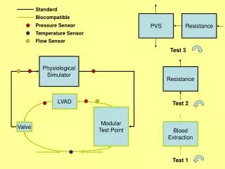
Interface Diagram • All measurements are going to USB-2416 DAQ unit • Voltage and current readings will produce power result • NI Labveiw will be used to view all the readings
Calibration Test Plan • Voltage Verification: • Use a DC power supply. Set it at a nominal voltage (5V) and connect leads to DAQ. DAQ should record the applied voltage of power supply (5V). • Verify actual voltage with multimeter • Current Verification: • Use a DC power supply. Set it at a nominal voltage (5V) and connect leads to the DAQ with a resistor in order to create voltage drop. DAQ should record voltage that is different from the applied voltage. Use Ohm’s law to calculate current in Labview • Verify actual current with multimeter • No calibration necessary for DAQ counters • Temperature Verification: • Submerge thermocouple in ice water and measure voltage • Submerge thermocouple in boiling water and measure voltage • Voltage and temperature have a linear relationship and temperature will be proportional to measured voltage • Contact Force Verification: • Attach calibrated weights to load cell and measure voltage • Voltage and force have a linear relationship and force will be proportional to measured voltage • Housing Torque Verification: • Attach calibrated weights to load cell and measure voltage • Voltage and force have a linear relationship and force will be proportional to measured voltage
Device Test Plan • All results will be viewed in Labview • Leads for current and voltage will be directly inserted into DAQ • For current acquistion a resistor may be needed • Voltage and current at the motor and generator will be used to calculate power • Efficiency will be calculated in Labview by: • Leads for thermocouples will be directly inserted into DAQ • Temperatures are read as voltages, which will be calibrated before testing • Leads from force gauges will be directly inserted into DAQ • Forces are read as voltages, which will be calibrated before testing • Forces will be converted to pressure by multiplying the measured force by the known area of the device • Leads for the Hall Effect sensors will be inserted directly into the counter inputs of DAQ • Counts will be converted into RPM’s