Download
1 / 25
280 likes | 485 Views
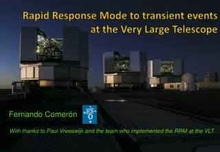
The Very Large Telescope Interferometer. Andrea Richichi European Southern Observatory. Neon School, Garching 29 August, 2008. Single Telescope. Interf. Fringes. Objects. Why is Interferometry useful?. Interferometry at your fingertips. Why is Interferometry difficult?.

E N D
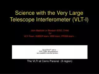
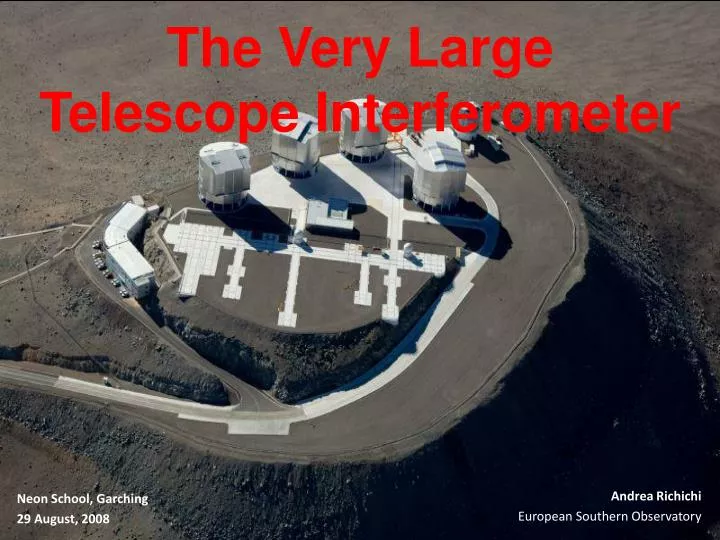
The Very LargeTelescope Interferometer Andrea Richichi European Southern Observatory Neon School, Garching 29 August, 2008
Single Telescope Interf. Fringes Objects Why is Interferometry useful?
Michelson Stellar Interferometer • Stellar source with angular size α0 • Add fringe patterns (i.e. intensities) between ± α0/2 • Resulting fringe pattern shows reduced contrast. • Reduced contrast depends on B – and on α0 . movies courtesy of A. Glindemann
Single telescope imaging vs. interferometry Sensitivity Diffraction limit
Optical vs Radio Interferometry In common: Visibilities, Closure Phases, Angular Resolution (λ/B) Radio: more baselines, phases, “true” imaging
VLTI Scheme The wavefronts must be “clean”, i.e. adaptive optics needed for large telescopes. The optical path difference must be continuously compensated by the delay lines. Atmospheric turbulence causes rapid fringe motion which must be “frozen” by a so-called fringe tracker.
Four 8.2-m Unit Telescopes (Baselines up to 130m) • Four 1.8-m Auxiliary Telescopes (Baselines up to 200m) • 6 Delay Lines • near-IR to MIR (angular resolution 1-20 mas) • Excellent uv coverage • 1st Gen Instruments • IR tip-tilt in lab • Adaptive optics • Fringe Tracker • Dual-Feed facility (PRIMA) • 2ndGen Instruments
correct sidereal path difference six delay lines combine all UT baselines combine almost all AT baselines laser metrology The “Paranal Express”
The VLTI Today + FINITO, IRIS, Differential Delay Lines, ARAL, vibration correction, ...
AMBER Medium Res 3 ATs IRIS FINITOoff FINITOon
How to obtain and use VLTI data • Public Archive (VINCI~20000 OBs, SDT, MIDI, AMBER): register as an Archive user • VINCI: pipeline • MIDI: MIA/EWS software (IDL) • AMBER: Ammyorick, Reflex • Write your own proposal
Interferometric Science Highlights • AGNs (dust tori) • Hot stars; massive stars; star formation • Evolved stars; dust in giants; AGBs • Stellar pulsation • Binary stars • MS stars and fundamental parameters • Search for exoplanets (direct detection) • Solar system (asteroids) • Black holes and relativity
NGC 1068 Incoherent combination 2 Tel coherent combination
Cepheid Stars • Radial velocity data (spectroscopy) • Angular diameter (interferometry) Perpendicularly to the plane of the sky In the plane of the sky Distance Relative size (Solar units) Angular diameter(mas) From P. Kervella (2005)
Evolution of the IBW method at a glance: Cep Mourard et al. 1997 Pulsation not detected Lane et al. 2000 First detection • Prototype Classical Cepheid • Interferometry is no longer the limitation to the IBW method • Individual V2 lead to / < 0.5% • Potentially*, the distance is determined at the 2% level • * How well do we trust LD & p-factor models ??? B=313m • Cep FLUOR/CHARA From A. Mérand (2005)
l Car Potential distance uncert. 11/545pc From J. Davis (2005)
The VLTI Tomorrow PRIMA Dual-feed facility Start of integration in Paranal in 2008 First scientific use in 2009 TBC 3-20µm, 4 beams 1-2.5µm, 4-6 beams 2.2µm, 4x2 beams MATISSE VSI GRAVITY Phase A studies concluded (Sep’07) for 2nd Generation Instruments
Conclusions • VLTI is well-developed, open, user-friendly facility • Flexible baseline system gives wide uv coverage • Most powerful combination of long baselines and large telescopes • Standard system of observation, data quality and data analysis • Diverse scientific issues at 0.001” resolution • Lively future