Download
1 / 26
630 likes | 1.41k Views
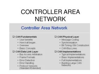
Controller Area Network (CAN). Introduction to CAN. Controller Area Network (CAN) is a serial communications protocol. CAN is widely used in automotive electronics for engine control, sensors etc. Layers of CAN. The CAN functionality is divided into two layers. 1) Data link layer.

E N D
Controller Area Network (CAN) Abhishek Kumar Srivastava
Introduction to CAN • Controller Area Network (CAN) is a serial communications protocol. • CAN is widely used in automotive electronics for engine control, sensors etc Abhishek Kumar Srivastava
Layers of CAN • The CAN functionality is divided into two layers. • 1) Data link layer. • 2) Physical layer. Abhishek Kumar Srivastava
Data link layer: - Data link layer is subdivided into two layers 1) Logical link layer: - • Accept the messages by filtering process, overloading notification and recovery management tasks will be taken care by this layer. 2) MAC (medium access control) layer: - • This layer will do the data encapsulation; frame coding, media access management, error detection and signaling and acknowledgment tasks. • Physical layer: - This layer deals with the bit encoding and de coding, bit timing, synchronization processes. Abhishek Kumar Srivastava
CAN properties • Multicast reception with time synchronization: Simultaneously multiple nodes can receive the frame. • Multimaster: When the bus is free any unit may start to transmit a message. • The unit with the message of higher priority to be transmitted gains bus access. • Prioritization of messages: Depending on the importance of messages the priorities will be given to the different messages. • System wide data consistency. Abhishek Kumar Srivastava
CAN properties • Arbitration: Whenever the bus is free, any unit may start to transmit a message. • If 2 or more units start transmitting messages simultaneously, which unit gets the bus access that will be depend on bitwise arbitration using the identifier. • The mechanism of arbitration guarantees that neither information nor time is lost. • Error detection and signaling. Abhishek Kumar Srivastava
CAN properties • Message Routing: An identifier names the content of a message. • The identifier does not indicate the destination of the message, but describes the meaning of the data, so that all nodes in the network are able to decide by message filtering whether the data is to be acted upon by them or not. • Remote Data Request: By sending a remote frame a node requiring data may request another node to send the corresponding data frame. • The same identifier names the data frame and the corresponding remote frame. Abhishek Kumar Srivastava
CAN properties • Automatic retransmission of corrupted messages as soon as the bus is idle again. • There is a distinction between temporary errors and permanent failures of nodes and autonomous switching off of defect nodes. • Configuration flexibility: Any number of nodes can be added to or removed from the system without doing any modification in software or hardware parts. • Bit rate: The speed of CAN message transfer may be different in different systems. • But for a given system the bit rate is uniform and fixed. Abhishek Kumar Srivastava
CAN properties • Single Channel: The bus consists of a single channel that carries bits. • The way in which this channel is implemented is not fixed. • E.g. single wire, two differential wires, optical fibres, etc. • Bus values: The bus can have one of two complementary logical values: ‘dominant’ (‘0’) or ‘recessive’ (‘1’). • During simultaneous transmission of ’dominant’ and ’recessive’ bits, the resulting bus value will be ’dominant’. Abhishek Kumar Srivastava
CAN properties • Acknowledgment: All receivers check the consistency of the message being received and will acknowledge the transmitter by sending dominant bit in acknowledgement field in case of proper message reception • Sleep/Wakeup mode: To reduce the power consumption CAN-device may be set into sleep mode without any internal activity and with disconnected bus drivers. • Inter-frame spacing data frames and remote frames are separated from preceding frames by inter-frame spacing field. Abhishek Kumar Srivastava
Types of CAN • There are two types of CAN implementations depending in the size of the identifier field. 1) STANDARD: 11-bit wide identifier field. 2) EXTENDED: 29-bit wide identifier field. Abhishek Kumar Srivastava
CAN message types • Data frame • Description: - Carries data from a transmitter to the receivers. • Fields: - Start of Frame, Arbitration Field, Control Field, Data Field, CRC Field, ACK Field, End of Frame. • Format: - Abhishek Kumar Srivastava
SOF: Start of frame bit. It is the indication of start of frame when a dominant bit is detected after the bus idle condition. • Arbitration: The arbitration field is depending on the type of frame. Abhishek Kumar Srivastava
This field contains: • Identifier field: contains information’s about message. In case of standard frame the length of this field is 11 bits and in case of extended 18 more bits are added to it . • So in case of extended frame total size of identifier field it is 29 bits. • SRR: one bit wide. Used in case of extended frame. • SRR bit will be recessive and in case standard frame this bit replaces the RTR bit. Abhishek Kumar Srivastava
RTR: one bit wide. Indicates that incoming frame is a data frame or a remote frame depending on the value of this bit. • If it’s a dominant bit implies incoming bit stream is of data frame else if recessive then remote frame. • IDE: one bit wide. Indicates that the incoming frame is of standard format if dominant bit is received in this field or else extended one (if recessive). • Control field: six bit wide. Two bits r0 and r1 are reserved. • In standard frame, r1 is replaced by IDE bit and remaining 4 bits called as data length control (DLC) describes total length of data field. Abhishek Kumar Srivastava
Data field: contains the actual information within the limit of {0…8} bytes. • CRC field: 16 bit wide. Divided into two parts: • CRC sequence: 15 bit length. Calculated over SOF to data field. • CRC delimiter: 1 bit recessive bit. • ACK field: 2 bit wide and contain two fields ACK flag and ACK delimiter. • ACK flag: being successful reception of frame the receiver will indicate the transmitter by putting a dominant bit in this place. Otherwise recessive. • ACK delimiter: A recessive bit. Abhishek Kumar Srivastava
END OF FRAME: 7 bit wide. Consists of 7 recessive bits. • Inter-frame space: 3 bit wide. Two continuous frames are separated by inter-frame space. Normal inter-fame bit values should be recessive. Abhishek Kumar Srivastava
2. Remote frame: - • Description: - Transmitted by a bus unit to request the transmission of the data frame with the same identifier. • Fields: - Start of Frame, Arbitration Field, Control Field, CRC Field, ACK Field, End of Frame. • Format: • Remote frame is similar to data frame except that it will not contain data field. • RTR bit is used to indicate the remote frame. Abhishek Kumar Srivastava
3. Error frame: - • Description: - Any unit on detecting a error transmits an error frame. • Fields: - Error flag and Error delimiter. • Format: - Abhishek Kumar Srivastava
As shown in above figure there will be two fields in error frame, error flag and error delimiter. • There are two types of error frames are there in CAN 1) Active error frame: Error flag -6 dominant bits. 2) Passive error frame. Error flag -6 recessive bits. • In both the cases all the bits of error delimiter will be all recessive. • Depending on the node internal error count register condition, the respective type of error frame will be transmitted. Abhishek Kumar Srivastava
Types of Errors • There are five types of error are there in CAN and are listed below. • And in case any one of these error is observed the error frame is transmitted. • Bit error: During transmission the node transmits the bit at transmit time region and receives the bit at receive time and two bits are compared if they are not equal then that is considered as bit error. Abhishek Kumar Srivastava
Stuff error: In a frame if continuous 5 recessive or dominant bits are transmitted, the sixth bit should be of opposite to that. • While receiving if continuous 5 recessive or dominant bits are received then the next incoming bit is of same value that of previous then it will be considered as stuff error. • CRC error: While receiving data or remote frame the CRC value will be calculated and is compared with the received CRC values. • In case of proper frame transmission both will be equal. Else that will be considered as CRC error and error frame will be transmitted. Abhishek Kumar Srivastava
Form error: Form error will be related to the error in forming the frame. • For e.g. delimiter (CRC, ACK) missing or improper end of frame, these conditions are taken as form error and immediately error frame is transmitted. • Acknowledgement error: During the transmission of dataor remote frame, in the ACK flag field, the transmitter will put recessive bit and expect dominant bit from receive pin. • If dominant bit is observed then that is considered as proper transmission. In other case it is acknowledgement error. • The error frame is transmitted if acknowledgment error is observed. Abhishek Kumar Srivastava
Depending on node state the active error frame or passive error frame is transmitted. • The error frame is transmitted immediately if error found is of type other than CRC error. • And in case of CRC error the error frame will be transmitted immediate next bit of ACK delimiter. Abhishek Kumar Srivastava
4. Overload frame: - • Description: - Detection of any one of overload condition make node to transmit overload frame. • Fields: - Overload flag and Overload delimiter. • Format: - • As shown in above figure, there will be two fields in overload frame, overload flag and overload delimiter. Abhishek Kumar Srivastava
Thank You !! Abhishek Kumar Srivastava