Download
1 / 18
260 likes | 634 Views
Equivalent Circuits - Resistors. Resistor noise is dominated by thermal noise:. Noisy Resistor. Noiseless Resistor. Noise Source. Networks of Resistors. Noiseless Resistor. Noise Source. Noiseless Resistor. Noise Source.

E N D
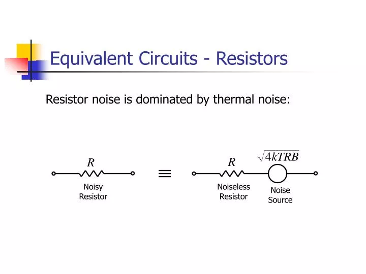
Equivalent Circuits - Resistors Resistor noise is dominated by thermal noise: Noisy Resistor Noiseless Resistor Noise Source
Networks of Resistors Noiseless Resistor Noise Source Noiseless Resistor Noise Source NB. When adding noise sources, the result is the root of the sum of squares.
Transistors Usually, only consider noise sources associated with the base-emitter junction. These will be magnified by the gain of the amplifier. en in
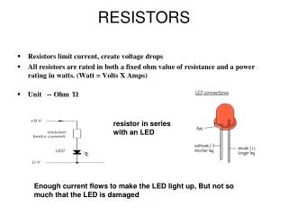
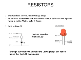
Base Spreading Resistance, rbb • Base spreading resistance, rbb, is the small, real resistance between the base terminal (the wire) and the actual base region of the transistor. • Typical values are 100 W or less. • It is small enough to ignore in most circuit analysis. • It is, however, a source of thermal noise.
Noise voltage sources We know that : re is not a real resistance so it doesn’t generate any thermal noise. ic, however, will be contaminated by shot noise, therefore generating a noise voltage across vbe.
Noise current, in, is dominated at high frequencies by shot noise in the base current. Noise Sources in Transistors Noise voltage, en, consists of thermal noise from rbb and shot noise in the collector current generating a voltage across re.
Noise in Real Transistors • Both the voltage and current noise sources will also contain a degree of flicker noise. • This may dominate at low frequencies but be insignificant at high frequency. • It is device dependent. • Usually, plots of en and in for varying collector current and frequency are given in data sheets.
Noise Figure of amplifier: Low Noise Amplifier Design Noise voltage resulting from en and in:
Noise Figure vs. Source Resistance 14 12 10 8 Noise Figure [dB] 6 4 2 0 1 2 3 4 10 10 10 10 Source Resistance [W]
Minimum Noise Figure To minimise noise figure, must minimise the term:
Noise Figure vs. Collector Current • Usually, the source resistance is fixed (e.g. transducer output impedance) • Noise figure can then only be optimised by either: • Scaling the impedance with a transformer • Choosing an appropriate collector current
Noise Figure vs. Collector Current Example, rbb = 100 W, b = 250, RS = 600 W
Optimising IC To minimise NF, with respect to IC, minimise:
Optimising IC (cont) Minimum when derivative w.r.t. IC = 0
Theoretical Example A low noise common-emitter amplifier is required using a transistor with rbb = 100 W and b = 250. The source resistance, RS = 600 W.
Practical Low Noise Design • Approximate expression for noise current neglects flicker noise • It is, therefore, only valid at higher frequencies where flicker noise is low. • For lower frequency design, either incorporate flicker noise in the equations or, more commonly, use noise figure plots provided in data sheets
Summary • In most amplifier circuits, the major sources of electrical noise are the source resistance, biasing resistors and the transistor/op-amp used for the input stage. • As the source resistance is usually fixed, the optimal output signal-to-noise ratio can be achieved by minimising the Noise Figure. • With transistor amplifiers, NF can be minimised by optimising the collector current: • Using the approximating equations • Using noise figure plots from a data sheet