Download
1 / 14
140 likes | 297 Views
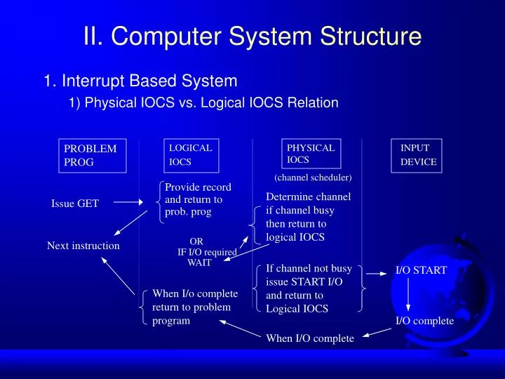
PROBLEM PROG. LOGICAL IOCS. PHYSICAL IOCS. INPUT DEVICE. (channel scheduler). Provide record and return to prob. prog. Determine channel if channel busy then return to logical IOCS. Issue GET. Next instruction. OR IF I/O required WAIT. I/O START. If channel not busy

E N D
PROBLEM PROG LOGICAL IOCS PHYSICAL IOCS INPUT DEVICE (channel scheduler) Provide record and return to prob. prog Determine channel if channel busy then return to logical IOCS Issue GET Next instruction OR IF I/O required WAIT I/O START If channel not busy issue START I/O and return to Logical IOCS When I/o complete return to problem program I/O complete When I/O complete II. Computer System Structure • 1. Interrupt Based System • 1) Physical IOCS vs. Logical IOCS Relation
II. Computer System Structure • 2) A kind of Interrupt • - External Interrupt • : Timer, Key on Console , Signal from other process • - SVC Interrupt • : Super Visor Call Interrupt • - I/O Interrupt • : I/O completion or Error occurrence • - Machine Check • : Error of machine in System • - Program Check • : Execution Error of Program • ( Divide by 0 , Error instruction)
II. Computer System Structure • 3) The Processing of Interrupt Program begin Program Interrupt begin Interrupt execute Interrupt process routine Interrupt complete
II. Computer System Structure • System Operation • User mode • Monitor mode • - Supervisor mode • - System mode • Dual-mode operation ( Context Switching ) • ex) Program execution (1) (3) Program execution User mode System mode (2) Interrupt execution
II. Computer System Structure • 4) Relation of New, Current and Old_PSW in INTERRUPT - I Location of next instruction SUPVR PRG 74 009138 Current PSW PRGIOI 1 2 4 ADD A, B PRGEXT 58 18 PRGIOI ADD C, K PRGSVC 60 20 PRGPCK 68 28 3 PRGMCK 70 30 PRGIOI 78 009138 38 New PSW Old PSW
II. Computer System Structure • 4) Relation of New, Current and Old_PSW in INTERRUPT - II Location of next instruction SUPVR PRG 74 009138 Current PSW 7 8 ADD A, B PRGEXT 58 18 PRGIOI ADD C, K PRGSVC 60 20 PRGPCK 68 28 PRGMCK 70 30 PRGIOI 78 009138 38 5 New PSW Old PSW 6
II. Computer System Structure • 2. I/O Interrupt • 1) Processing I/O Requests Relationship • - Without I/O interruption 1 2 3 4 5 6 processing F1 Waiting for I/O completion I/O wait processing Waiting for I/O completion F2 I/O wait processing F3 I/O wait SUPVR task selection task selection task selection ALL BOUND SYSTEM in wait state Active state Inactive state I/O
Waiting for I/O F1 Waiting for I/O Waiting to be selected F2 Waiting for I/O Waiting to be selected F3 SUPVR Posting Traffic Bit & Performing Task Selection System in wait state F1 F2 F3 I/O interrupts II. Computer System Structure • - Case of I/O interrupt • I/O interrupt sequence • F1 : s I/O interrupt occurs • F2 : s I/O interrupt occurs • F3 : s I/O interrupt occurs
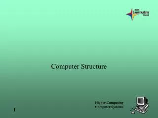
Read-write head track actuator sector cylinder platter rotation arm II. Computer-System Structure • 3. Storage Structure • Main-memory : volatile storage device ( Register, cache ) • Magnetic Disk : sectors track cylinder package • Magnetic Tape : backup, infrequently, transfering
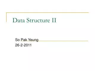
Register cache main memory electronic disk magnetic disk optical disk magnetic tapes II. Computer-System Structure • 1) Storage Hierarchy • - Caching : by cache size, replacement policy 80~99% • - internal programmable register • ex) index register, Accumulator • - cache coherency & consistency (a copy of A ) • in a multiprocessor • in a distributed environment Storage Hierarchy
II. Computer-System Structure • 2) H/W Protection : for system utilization • - To share system resources • SPOOL • multiprogramming • - Dual mode operation • user mode • monitor modesupervisor mode • system mode • privileged mode • privileged instruction : executed in busy monitor mode • ex) I/0 instruction , Timer ...
0 base + limit base 256000 300040 base register 300040 120900 Monitor yes address yes CPU 420940 limit register no job 1 no 880000 1024000 job 2 trap to operating system monitor - addressing error memory job 3 job 4 II. Computer-System Structure • - Memory protection • Base register • Limit register A base and a limit register define a logical address space. Hardware address protection with base and limit registers.
trap to monitor return to user II. Computer-System Structure • -CPU protection : Infinite loop - Timer : Control OS X • - System Call (monitor call) : Process OS Interface resident Case n monitor perform I/O read system call n user program Use of a system call to perform I/O.
Speed up n II. Computer-System Structure • 3 ) Multiprocessor Systems • - Throughput : n processor n speed up ratio • - Reliability • - fail-soft : 1 gain in 10 processor graceful degradation • Symmetric multiprocessing : Same O.S copy • ex) Tandem system • Asymmetric multiprocessing : a master processor with slave processors